I've never heard a cap make ANY noise whatsoever that wasn't outgassing, shorting inside, or ready to explode. By nature, they have no moving parts, and shouldn't make noise. Even if they have an excessive load on them. You could measure the current on that side of the powersupply, but the cap still shouldn't make noise.


You are using an out of date browser. It may not display this or other websites correctly.
You should upgrade or use an alternative browser.
You should upgrade or use an alternative browser.
Filter cap buzz....should I worry?
- Thread starter z-adamson
- Start date
If the ripple is about the same on both positive and negative rails and a reasonable value (depends on amp, class... 50-250mV)If it passes the ripple test, the circuitry outside of the filter caps is ruled out as a culprit, right? At that point, filter cap replacement is the next step, right?
then both caps are doing their job and can rule out ripple as cause of noise. If one cap has excessive ripple, eg 5Vp-p
then maybe that cap is not holding it's charge/leaking to gnd or something on that rail/side of the amp is consuming
excessive power

northpaw
Super Member
While an oscilloscope is a superior tool for chasing hum/ripple, a DMM set to AC volts will show an ~RMS value for ripple. All that you have to do is place the probes across the + and - lugs of the capacitor to measure the ripple across it. As mbz says, several tens to perhaps a hundred mv (RMS in this case) is normal, and should be about the same for the caps on each side of the power supply. While you are in there, you can also measure the DC volts across the same lugs; these values should match the PS spec for + and - volts DC, and also should be about equal but of opposite polarity for the two sides. In my experience with failed PS filtering caps, if you have significant ripple, the DC voltage on that side will be significantly reduced. The more the AC ripple, the more the reduction in DC voltage.
But the fact that the OP has already reported that there is no buzz through the speakers already indicates, IMO, it is unlikely there is excessive ripple across the suspected cap(s).
The other question that bears asking is if the OP is absolutely sure it is that one cap that is buzzing, and not the nearby transformer? Mechanical buzz of the transformer, without buzz through the speakers, is not uncommon.
In my experience, if you need to place your ear next to something in order to localize it, distances of a couple of inches can be hard to distinguish. Also, knowing the frequency of the buzz can help: 60Hz for the transformer, 120Hz for post-rectification (e.g., the caps). Again, an oscilloscope is superior tool for this, but an audio frequency plotting app like Spectroid on a phone or tablet can tell you what you want to know. It also has the benefit that you can place the microphone in the phone more precisely than you can place your ear, giving grater confidence in identifying the actual source of the buzz.

z-adamson
Addicted Member
Definitely the cap that buzzes. It is a different kind of buzz than transformer buzz....it has a crackle type of sound to it. But, still a buzz. And when I press down on the cap, the sound changes. Sometimes drastically. The transformer is very quiet and i am confident that the source if the buzz is the cap.While an oscilloscope is a superior tool for chasing hum/ripple, a DMM set to AC volts will show an ~RMS value for ripple. All that you have to do is place the probes across the + and - lugs of the capacitor to measure the ripple across it. As mbz says, several tens to perhaps a hundred mv (RMS in this case) is normal, and should be about the same for the caps on each side of the power supply. While you are in there, you can also measure the DC volts across the same lugs; these values should match the PS spec for + and - volts DC, and also should be about equal but of opposite polarity for the two sides. In my experience with failed PS filtering caps, if you have significant ripple, the DC voltage on that side will be significantly reduced. The more the AC ripple, the more the reduction in DC voltage.
But the fact that the OP has already reported that there is no buzz through the speakers already indicates, IMO, it is unlikely there is excessive ripple across the suspected cap(s).
The other question that bears asking is if the OP is absolutely sure it is that one cap that is buzzing, and not the nearby transformer? Mechanical buzz of the transformer, without buzz through the speakers, is not uncommon.
In my experience, if you need to place your ear next to something in order to localize it, distances of a couple of inches can be hard to distinguish. Also, knowing the frequency of the buzz can help: 60Hz for the transformer, 120Hz for post-rectification (e.g., the caps). Again, an oscilloscope is superior tool for this, but an audio frequency plotting app like Spectroid on a phone or tablet can tell you what you want to know. It also has the benefit that you can place the microphone in the phone more precisely than you can place your ear, giving grater confidence in identifying the actual source of the buzz.
Dc volts across each cap is the same number.


z-adamson
Addicted Member
Odd that your oscilloscope has red and black probes. Normally one of the probes has a wire with an aligator clip
or similiar attached. It is this clip/wire that should be connected to chassis.
This is how i am using the scope.
Does this seem wrong?
You see the layout of the leads, the chassis ground and the probe to the filter cap.
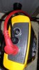


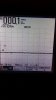

z-adamson
Addicted Member
The other cap...the one that buzzes. Ironically, it didn't start buzzing till I started to probe the solder pads. It is as though pushing against the pad just hard enough to get a good reading made it start to buzz. Again, the straight line wave forms are of the filter cap terminal that does not bridge to the other filter cap. There are 2 of these straight lined waveforms....the value moved around a little as the buzzing got worse. Pushing against the solder pads with scope leads definitely aggrivates the buzzing.


Last edited:
Trying to work out what your traces show.
Text book ripple looks like this,

The dotted lines are the rectified 50/60Hz AC. peaks are 8-10mSec apart, so set time/div to 5-10mS/div.
The red line is what you are looking for. The rectified AC charges up the cap, when the AC drops down, the cap
discharges a little until the next charging cycle. Would like to confirm that the voltage swing of the red line is not
too large.
Post #28 Like the UCC's.
Post #30 maybe use the phono GND as earth. Also try any black speaker post as GND (for common GND amps only)
Post #31, #32 in bottom left corner there is an "A-" I take this to mean DC. Do you see any way to switching to AC
on your tester.
Text book ripple looks like this,
The dotted lines are the rectified 50/60Hz AC. peaks are 8-10mSec apart, so set time/div to 5-10mS/div.
The red line is what you are looking for. The rectified AC charges up the cap, when the AC drops down, the cap
discharges a little until the next charging cycle. Would like to confirm that the voltage swing of the red line is not
too large.
Post #28 Like the UCC's.
Post #30 maybe use the phono GND as earth. Also try any black speaker post as GND (for common GND amps only)
Post #31, #32 in bottom left corner there is an "A-" I take this to mean DC. Do you see any way to switching to AC
on your tester.

petehall347
the brandy coffee man
is the screw tight that sits between the caps ? just a thought .
z-adamson
Addicted Member
Yesis the screw tight that sits between the caps ? just a thought .
z-adamson
Addicted Member
I will try this again later. Scope was set to ac, auto adjust. There is a pulldown menu that allows the user to switch between ac and dc.Trying to work out what your traces show.
Text book ripple looks like this,
View attachment 1619050
The dotted lines are the rectified 50/60Hz AC. peaks are 8-10mSec apart, so set time/div to 5-10mS/div.
The red line is what you are looking for. The rectified AC charges up the cap, when the AC drops down, the cap
discharges a little until the next charging cycle. Would like to confirm that the voltage swing of the red line is not
too large.
Post #28 Like the UCC's.
Post #30 maybe use the phono GND as earth. Also try any black speaker post as GND (for common GND amps only)
Post #31, #32 in bottom left corner there is an "A-" I take this to mean DC. Do you see any way to switching to AC
on your tester.
I will manually set it to 5-10msec per division.
What should I manually set the voltage to?
Not sure where to find phono ground.
Phono GND is typically a "bolt or screw" located near the PHONO RCA's at the rear.
Having another look at those traces, seems I've mis-interpreted
The first trace shows -72.4Vdc with 100mV ripple
The third trace shows +72.4Vdc with 600mV ripple
The question then becomes is it the cap on the positive rail that's making the noise.
600mV is not excessive, barely enough the tickle the UCC SMH 10000uf/80V caps.
Rated ripple 6.63A, not huge but...
The +ve rail probably has some extra loading like the tuner stage and the light show.
Maybe you just got a dud cap. Are the solder connections ok?
Does the noise stop if you apply light downward pressure on the cap using something
non-conductive eg, chop stick.
Consider switching the caps, means a bit of work.
z-adamson
Addicted Member
@mbz
The noise definitely changes pressing on the top of the cap and pressing from the bottom at the solder pads.
I don't see anything to indicate a problem at the solder joints.
I will probably replace the cap unless I find something else to explain the problem. The noise is somewhat alarming even if the ripple is within tolerance.
I will play around with this some more.
Still not sure why I couldn't get a textbook ripple waveform.

gslikker
Super Member
Some usually lesser brands/types of cap have smaller innards inside, giving room to mechanical instability. Here the lightweight caps I got scavenged from professional old equipment.
Of course, the company using them was probably unaware of the lesser quality when new. If the cap is loose in the can, it can move.

Of course, the company using them was probably unaware of the lesser quality when new. If the cap is loose in the can, it can move.