• The move to the new server is done. There are some software and database maintenance updates in process. This has us passing the hat around to help out. We appreciate any donations. Seriously, even a dollar helps. The payment page may be found here - https://www.audiokarma.org/support.html

Fisher 201 receiver no tuner output

SDsailor7

AK Subscriber
Subscriber
Hi all,
I am working on my Fisher 201Futura series receiver due to no output from the FM or AM section.
The other functions work fine.
I found that transistor Q01 Hitachi 2SD1061 is not working properly, no voltage output from emiter side.
I was reading some of the threads on the forum and some of the replacements are MJE15034,MJE15032 and KSD526 the MJE's are obsolete not carried by mouser or digikey. KSD526 is carried by mouser. Will that be a suitable transistor for my Fisher 201 receiver? Or are there others better suitable than the KSD526?
Thank you in advance for any help provided.
 
Register to hide this ad
Before replacing Q01, might want to check that there is +16 volts on the base of Q01, and +48 or a bit more on it's collector. Not uncommon for those Zeners to fail (D05).
 
@dimanag,
either i forgot that g or they did not list it on the thread i read.
Thank you i will look it up again in mouser and will include the g.
@Ylli,
I did check the voltages Base was 15.86vdc and collector was 51,44vdc so i assume D05 is good uh? so i should put in my order at mouser now?
 
With 51 volts on the collector, 16 volts on the base and zero on the emitter, the transistor is certainly bad. I would suggest you order more than one so that if the trouble is downstream and you blow out the first replacement you still have another good one. Parts are generally cheap - shipping is $$.
 
@Ylli, Yup i was thinking that. It is a good idea to have spares. I will combine my order with another for a Heathkit IM-28 vtvm that i bought needs new capacitors.
I will report back when i install the transistor on the fisher and the results i get.
Thank you
 
The fisher is alive!:)
Hi all,
I received the transistors that i needed today so i replaced the bad transistor in the power supply board and got sound back now i can test the other functions like cassette, phono, aux 1 and 2 to see if they are working without issues.
I did notice that the stereo light and the lighting for the signal strength is not there i checked the wiring going to the lamps and i am getting 15.5vdc on both legs of both lamps i then traced tha wires to the multiplex board and on FMSS i get 15.5vdc and on PL (pilot lamp?) i get 8vdc.
The schematic shows one wire going to FMSS and the other to FM and i did not find a FM on the board. Any ideas as to where to check next?
I had the receiver set to a FM station and i was getting a strong signal the meter was showing 4 on the scale.
Thank you
 
There are resistors across both 'stereo lamps' which are likely disguising burned out bulb(s). The meter lighting appears to be simply tied to the 6VAC - dial lamps, pointer lamp and meter lamps all in parallel. Again, most likely just burned out bulbs.
 
@Ylli,
I checked the purple and blue wire that are supposed to have 6vac supplying the back of the station dial and i am getting 3.82vac on the purple and 0.73on the blue wire the thing i don't understand is that my station dial and the station pointer are still illuminated? there is a mica strip were the blue wire goes and from there there are jumper wires that connect to a green wire that goes to the back of the station dial were the purple wire is also connected to. I was trying to remove one of the lamps from the stereo indicator housing to inspect it and i broke one of the wires on one of the lamps, bummer :-( now i will have to buy another bulb.
There are also four skinny wires that are connected to the back of the station dial and only one side is connected the other ends are not connected so i don't know where they go? the schematic does not show the how they are connected. I am wondering if they go also on the back of the station dial?
 
@Ylli,
I checked the purple and blue wire that are supposed to have 6vac supplying the back of the station dial and i am getting 3.82vac on the purple and 0.73on the blue wire the thing i don't understand is that my station dial and the station pointer are still illuminated?
The 6VAC line is not grounded anywhere - you would need to measure the AC voltage *between* the two wires.
Screenshot 2022-04-22 153447.jpg
there is a mica strip were the blue wire goes and from there there are jumper wires that connect to a green wire that goes to the back of the station dial were the purple wire is also connected to.
All the meter, pointer, and dial lamps are wired in parallel.
I was trying to remove one of the lamps from the stereo indicator housing to inspect it and i broke one of the wires on one of the lamps, bummer :-( now i will have to buy another bulb.
The manual has no parts list, have no suggestion as to the type of bulb to replace it with. Might want to ask in the 'Tuner' sub-forum.
There are also four skinny wires that are connected to the back of the station dial and only one side is connected the other ends are not connected so i don't know where they go? the schematic does not show the how they are connected. I am wondering if they go also on the back of the station dial?
All the lamps except the stereo indicator lamps are wired in parallel per the schematic.
 
@Ylli,
I checked the voltage between the blue and purple wires like you suggested and i am getting 5.56vac so it is about right. I am wondering if they changed the original dial light bulbs to LED and that is why the four green skinny wires are only soldered on one of the terminals.
One of the screws that hold the light bulb cluster is stripped the other one is ok. So if i wanted to verify i would have to fight with that screw.
Another thing i learned was that the transistor i replaced on the power board is missing the heath sink, would the transistor fail over time without the heathsink? or do i need to make one?
 
@Wlli,
I managed to get one of the "stereo lamps" out, the one with the broken lead and the bulb is not burned i also was able to get the other light bulb out and it also not burned and getting 15.40vdc
The schematic shows 15.5vdc so i am in the ballpark and the light should work but is not.
So what am i missing? both light bulb leads get the 15.5 volts. Thea readings i got are: 15.40, 15.40 and 14.82 due to the broken lead.
The dial and pointer lights are working fine. I am baffled as to why the light bulb wont come ont? is it because the other is not working and the lead is broken?
Also see post above please.
 
Heat sink: Not all transistors of this style have a heat sink attached. Are you sure it is missing or do you just think it should have one? If there is room, adding one wouldn't hurt. Just be sure it does not short to anything (the transistor metal tab is also the collector) and that it is mechanically secure so that vibrations don't end up breaking the transistor's leads.

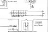
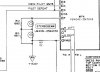
Stereo lamps: How did you determine they were good? What voltage do you see at the MPX board terminal 'PL' when tuned to a stereo station and when tuned between stations? Attached the schematic snippet - might want to check the wiring. A lamp, even an LED will not work with only one wire attached.
Screenshot 2022-04-24 102628.jpg
 
Hi Ylli,
I was looking for a repair video of the fisher on Youtube and found one of a guy that showed the operation of the receiver after he had restored it and provided a link to a page that showed a detailed restoration with pictures (no video) the YT video is fisher 202 vintage receiver demo after restoration and the poster is Oleg's Vintage audio. In the webpage he shows before and after readings of components and what components he used to replace them and readings after replacement of the components. And in those pictures is where i saw the transistor with the heatsink/support and it is not a homemade heath sink.
But if the transistor is ok without a heat sink i would leave it like that, I was just concerned about the disippation of the heat.

On the lamps i determined that they were good by visually looking at them. I also took voltage measurements and the good lamp was getting 15.5vdc one one leg and 15.0vdc on the other one. The light bulb with the broken leg i did not check because of that.
Onthe MPX at FMSS i get 14.40vdc and 14.88vdc at PL with a station in stereo (strongest signal on the stereolamp dial) In a weak station i get 14.55vdc on FMSS and 14.90 at PL

Question: I thought that light bulbs are supposed to get voltage on one leg and the other one is for ground? i get voltage on both legs of the light bulb.

I asked the guy that posted the YT video about the problem i was having and he said check transistor TR6 on the MPX board and i did earlier this morning and this is what i got.
Collector 14.80vdc, Base 0.49vdc, Emiter 0.00 So that transistor appears to be not working?
Your thoughts?
 
Earlier you had said something about 8 V at PL. That would have put 7 volts across the lamps and should have turned them on. But if you are now seeing +15 volts at PL, there is likely an issue with the MPX board. Base voltage on TR6 of 0.49 volts is not enough to turn it on. So that does not say the transistor is bad . What voltage do you see at TP3 (on the MPX board) with a stereo signal being received?
 
Yes that is correct, I was getting 8vdc on PL buy the lamps would not go on.
I will check the voltage on TP3 and report back on the findings.
Thank you for the help Ylli
 
Here are the readings i got from TP3 which is one leg of R10 resistor. 3.71vdc, PL now measured 3.0vdc FMSS14.57vdc and tuner set to a good signal stereo station.
 
Back
Top Bottom