• The move to the new server is done. There are some software and database maintenance updates in process. This has us passing the hat around to help out. We appreciate any donations. Seriously, even a dollar helps. The payment page may be found here - https://www.audiokarma.org/support.html

Fisher 20a, pondering possible upgrades

nerdorama

AK member
Subscriber
I am receiving a pair of these from a friend who is also keeping a second pair. He asked if I could determine whether there are improvements that could be made in the interest of both sound quality and tube life. Just wondering if possibly EFB could be adapted to any benefit on this amp. I looked at the article about the SA100. It appears that if I derived a bias voltage from the B+ winding I could do the EFB project but not sure if it would be worth the trouble for either of the goals stated here. The EL84's are being run well beyond the 12W max rating so it would be easy to change the cathode resistor to bring the bias current down a bit. As well the screens are a fair bit above the 300V max rating. If adding an EFB circuit I could also add a balance control for an added touch. These might already have chokes added to the power supply.

I think he will be bringing these by today so am just pondering at this point.
Thanks,
John
 
Register to hide this ad
This guy right?


EFB for cathode and screen regulation would be a nice improvement. I expect that screen supply voltage shifts quite a bit under load. Fair bet you could end up running it at lower current and get much better distortion performance too. they really are running the snot out of those output tubes.

depending on the assembly, maybe modify the heater string to be balanced instead of just running one side to ground, and elevate it by ~30v or so.
 
This guy right?
That's the guy. The indicated OPT primary resistances, if they are correct, are quite far apart. Makes me think they weren't wound with much interleaving of the layers. Probably ok but I wonder. I have them now and later today I'll start in with some measurements.
 
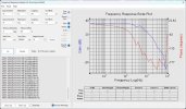
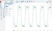
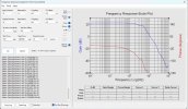
Got a few FR measurements. I wanted to get a feel for how it does open loop and with varying feedback components installed. It appears to have about 10dB of feedback. It's a little raggedy in the supersonic region and the phase seems to hit 180deg before the gain falls below zero. A 1kHz square had some HF ringing on the leading edge and the 10k square was quite ragged. I might try a shelf network on the VA plate load. It also strikes me that the first stage gain is rather high with a 470k plate load. It only took 0.2v peak on the input to hit 1W at 1kHz.

Open loop:
Fisher 20a No1 FR no feedback or comp ~1W.jpg

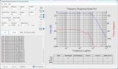
With the stock feedback and shunt cap:
Fisher 20a No1 FR as received ~1W 8ohm.jpg
 
Maybe with tuning it could accept more feedback to have a more appropriate input sensitivity. Looks like C4 and C5 may have different values in some amps, so maybe it was a later revision?
 
right, what I meant was they seem to have changed those values at some point, curious what the reasoning for that was.
 
Do you have or know of an older schematic? I can't find anything other than the Sam's that I'm using.
 
More testing and experimenting today. As of now the feedback resistor and phase advance cap are per schematic, 22k & 68p. I added a shelf network across the 470k input stage plate load of 15k and 200p. Still had a noticeable ringing on the 1k square wave leading edge. Tried several values of input grid stopper for some Miller low pass and ended with 100k. These output transformers have some funny stuff going on around 40k-50k which makes it hard to get a clean FR through 20k and keep things stable. I removed the 47p shunt cap from the grid of the phase splitter as with the shelf it didn't seem to do anything.

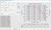
Final FR for today:
Fisher 20a No1 FR ~1W 22k_68p fdbk 15k_200p shelf 100k input grid 220ohm 31mA bias.jpg

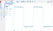
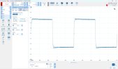
1k square still a bit of leading edge ringing but amplitude is much reduced with the 100k Miller grid stopper on the input.
Fisher 20a No1  1kHz square ~1W 22k_68p fdbk 15k_200p shelf 100k input grid 220 31mA bias.jpg

10k a bit ragged but so be it:
Fisher 20a No1 10kHz square ~1W 22k_68p fdbk 15k_200p shelf 100k input grid 220ohm 31mA bias.jpg
 
Tried bumping up the feedback. Seems ok but the phase seems to be creeping up relative to zero gain. HF at 20k is a little better and the 1k square wave ringing haven't gotten worse noticeably.

Fisher 20a No1  ~FR 1W 15k_68p fdbk 15k_200p shelf 150k input grid.jpg

Fisher 20a No1  1kHz square 1W 15k_68p fdbk 15k_200p shelf 100k input grid.jpg
 
I have no other schematic, just guessing based on the fact Sams indicates a value change. Must have been for some reason, no idea what that reason is.
 
The alternate feedback resistor is 15k rather than the 22k. Could be they weren’t safely stable with the greater amount of feedback. They aren’t too good even with the reduced feedback. The shelf network and the input grid stopper have made improvements. The OPT’s seem to have some problems in the 40-50kHz area which may be the reason.
 
try an output zoebel maybe?

may just be the transformers are not awesome. that 80 ohms of DCR difference sort of jives with that.

maybe as a thought, try grounding the 4 ohm and see what the squares look like on the 0 and 16, perhaps its suitable for cathode feedback.
 
Might try the cathode feedback test and see what they look like. For now I want to update the second unit and have a listen. Thanks for the ideas and comments. These amps must be a little uncommon as there isn't much written about them.
 
I'd never heard of one, though that doesn't mean much.

Based on the cage and such I'm guessing this must have been of the era of the "boxcar" style mono amps like the 80A.
 
HiFiEngine says it's from 1958 only. The 30a from 1959 only, It appears they didn't last long in the market.
 
that would have been about the point stereo was taking off, so not real surprised mono stuff went away.
 
Latest round. I added an inrush limiter to the AC and now I can run it at 120VAC in and it drops the voltage enough when warm that the heaters are almost exactly on 6.3V. At some point I'd like to get the heater current out of the chassis as one side is now grounded. Then I could add the resistors to make a CT and elevate the voltage a bit.

In spite of my best efforts that is not stable without a load if there is an input. It's ok with no load and no input. Maybe just the nature of this beast. I have decent performance with the original feedback resistor and cap and a shelf network which I have added. These appear to have been a budget model by Fisher based on what I'm seeing in both performance and construction. They are very cute with the "bread loaf" style of case. I looked at the 30a Sam's earlier today and it looks like a better design.

Here's where I'm at and will probably leave it for now.
Fisher 20a No1 FR 1W 22k_68p fdbk 22k_250p shelf 100k input grid.jpgFisher 20a No1 1kHz square 1W 22k_68p fdbk 22k_250p shelf 100k input grid.jpg
 
maybe as a thought, try grounding the 4 ohm and see what the squares look like on the 0 and 16, perhaps its suitable for cathode feedback.
Would be tough to do cathode feedback without changing to fixed bias. I checked the balance of the voltages relative to 4ohm tap and they seemed quite well matched, at least at 60Hz. I used a variac to energize the full primary at about 60VAC and got voltages that were withing 1mV of each other. But with cathode bias with a 220ohm resistor I don't see a good way to do cathode feedback. Still struggling with this amp. It like to ring on the 1k square wave and it seems to be around 50kHz so only and octave+ above the audio band. Hard to quell without rolling the FR down below 20k.
 
Not really hard, the resistance would sit between center tap and ground, though that does make the speaker terminals considerably positive vs chassis. Not enough to be dangerous but if it shorts you have toasted tubes.

If the mono preamp isn't used with this, you do have an extra 6v supply to work with.

Maybe worth the experiment to see if it even works well enough to put effort into.

I have done small value caps from an output tube plate into the feedback line to deal with HF nonsense. Also maybe possible to go across the primary in addition to a step network off the plate of the voltage amp. Another thought may be to use a different tap on the transformer for the GNFB connection, or use multiple taps to see if that irons it out.
 
Back
Top Bottom