• The move to the new server is done. There are some software and database maintenance updates in process. This has us passing the hat around to help out. We appreciate any donations. Seriously, even a dollar helps. The payment page may be found here - https://www.audiokarma.org/support.html

Fisher 20a, pondering possible upgrades

Incidentally, I tried adding a 12V Zener across the cathode resistor on a 433, and power at clipping went from 11W to almost 18W, without the crossover distortion appearing first. This essentially transitions to fixed bias once the cathode voltage begins to rise. A 1W Zener failed shorted when I drive it into hard clipping, but a 5W would be safe.
Yesterday I was trying to see where clipping would occur but I got notch distortion well before clipping. This morning I remembered talk about using a zener to clamp the cathode voltage rise and found this. The next post was yours mentioning that you did similar to a Fisher 600 with similar results. My cathode is right at 13.5V. I have both 14V and 15V 5W zeners. How close should I set the zener voltage to the 13.5V quiescent value?

I'll try a small cap from an output plate back to the summing node and see what happens. I've done that before but somehow haven't thought of it on this project. I'll have to determine which plate to use.

Thanks for the help with this.
 
it works, but EFB would also get you the same sort of results and be fully adjustable. Probably better since it tracks screen voltage as well. Reason I used the zener in the 600 was because the cathode resistor is the phono tube heaters, so EFB wasn't really a viable path. I can't claim credit for the idea, I borrowed it directly from @dcgillespie working on one of Fisher's other models that did the same sort of thing.

There is also some magic mod supposedly from Bob Carver on some Packard Bell console pull, claiming to be a DC restorer circuit. Its the same zener across the cathode resistor.

also you can probably tweak that cathode resistor value to drop the plate dissipation a bit. Part of why its so high is to prevent the bias from shifting so much under load, giving you more usable power before it develops crossover distortion. The zener would prevent that so the high idle point isn't as needed.

Either diode would probably work though, not sure if there is a big advantage to one over the other. Lower voltage would mean more peak current so maybe a little harder on the tube.
 
I added a 14V zener since my quiescent bias runs at 13.5V. I upped the cathode resistor from 125 to 220 just to keep dissipation within the spec of 12W.

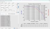
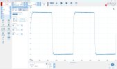
I tried some small caps from EL84 plate to summing node. Wasn't sure which tube to choose so I tried them both and chose the one that reduced the ringing. Ended with 3.3p. Tried some higher values and they cut the ringing more but started to roll off the FR more than I liked. With the 3.3p Fr is down about 2dB at 20kHz at ~1W and a little more at 13W+. The zener keeps the notch distortion at bay until around 14-15W where I can see it just barely come back but I'm hitting clipping around then so 15W it is. Not too bad.

Fisher 20a No1 FR ~1W 22k_68p fdbk 15k_250p shelf 100k input grid 3.3p plate fdbk.jpgFisher 20a No1 1kHz square ~1W 22k_68p fdbk 15k_250p shelf 100k input grid 3.3p plate fdbk.jpg
 
yeah one plate will be positive feedback, the other negative. Should make a pretty obvious difference which way is not correct.
 
It wasn't super obvious but I could tell by the amount of ringing on the leading edge. Since these belong to a friend I'm not ready to dig in deeply and do EFB but if they become mine, it's a possibility, I would look into it in more detail. I don't want to drill any extra holes in the chassis at this point. I would also like to consider installing a signal common buss and get signal currents out of the chassis. Maybe install a 3 wire power cord then. There are a handful of grounded terminal lugs that are rivetted and I remember DaveG have troubles on a SA-100 if I remember. I think he was able to soak them with Cramolin or something akin and after some soak time repunched the rivets with a center punch.
 
rivets for connecting ground to the chassis can be a problem, especially if they are carrying current. Have fixed loose rivets with punches or by soldering depending on the particulars.
 
Got the second amp tuned and buttoned up. This one required a different shelf network to match the FR of the first unit. It seemed to have more inherent HF rolloff than the first so needed a less aggressive shelf network. Listened for about an hour this morning. They are very nice sounding. Clean and clear with a super quiet background.

Took it home to my friend. It sounds pretty darn nice on his Altec A7's.
 
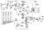
This is the schematic I ended with. Some of the voltages are a bit different. That could be caused by less than perfect tubes or other things.
Fisher 20a schematic as-built 20Jun26.jpg
 
Last edited:
Were the output transformer numbers the same? I wonder if they changed mfg or tweaked the winding pattern at some point.

Decided to leave the zener out?
 
Back
Top Bottom