• The move to the new server is done. There are some software and database maintenance updates in process. This has us passing the hat around to help out. We appreciate any donations. Seriously, even a dollar helps. The payment page may be found here - https://www.audiokarma.org/support.html

Fisher 800C consistent hum. Help needed!

Space. Looks like a lot of open flat chassis on that Fender, not so much on receivers or honestly most hifi gear. Even the stuff that doesn't need to be cramped often is. I guess they were saving pennies on the steel in the chassis or something, but way too many things are just way more cramped than makes any sense. Makes them miserable to work on too.
Many vintage guitar amps were engineered with the tech and maintenance in mind.
 
its more like commercial gear. That was also generally designed for reliability and serviceability. I highly doubt the people building consumer hifi stuff in 1960 thought we'd still be using it in 2025.
 
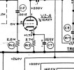
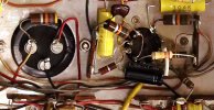
I offer some information that can be relevant to four section electrolytic capacitors. HH Scott used a lot of them having the two cathode resistor bypass capacitors inside the can with the two B+ filter sections. I have rebuilt (or replaced with JJ Capacitors, clamp mount) them by using the B+ sections only. Then, at the tube, I have placed the cathode resistor bypass capacitor. Today, the electrolytic capacitors are tiny in comparison to the "vintage" electrolytics. These bypass capacitors are small in value and voltage, being something around 25 µFD @ 25 VDC. See the example showing "C7". Just another option. Often, the resistor, R13 in this example is located on the capacitor, going from a lug on the capacitor to a lug on the mounting ring. That resistor can also be placed at the tube.

Just a thought.


bypass.jpg


Before.jpg


EDIT REASON: To add a before picture.
 
Last edited:
This is a different amplifier but an example of the "After" capacitor and resistor installation. The electrolytic capacitor on the left is a clamp mount used for B+ only and at the tube socket, you can see an example the bypass capacitor and resistor. Plenty of room for this modification.


After.jpg
 
I've done these this way too, it's acceptable because the small electrolytic is light enough that it doesn't stress the pins of the socket, and cheap/common enough that if it does fail due to heat in 20 years, who cares, slap in a new one and party on!
 
its also attached to something at both ends. The ones that bug me are where you see some big chunky cap hanging from just one lead and the other has a connection with 400 volts on it simply floating in space. I've done it for quick diagnostics but its not a great way to make a permanent repair.
 
index.php

Did you decide to keep the carbon comp resistors in the power rail, or was that the owner's decision?

Just a query. Thanks!
 
I left it as original as possible as long as they measured within tolerance. I (unfortunately) have found that many "purchasers" think that amplifiers loose their "sound" if you use new parts. All of these pictures are of amplifiers that were passed on to new owners.

Additional comments:

I have found that vintage Ceracaps that seem to test OK with no leakage are still suspect. When I test them for leakage, the often pass with flying colors. But when measured for value, using a vintage Cornell Dubilier (restored of course) Capacitor tester, the edges of the eye tube are not crisp. Rather they are fuzzy. An engineer that I know says that it is too much dielectric dissipation caused by the Mylar breaking down in old capacitors.

But some Ceracaps that were installed toward the end of Scott's vacuum tube era are still good. Pyramid or "Bumble Bee" capacitors are always no good. Yes, they could be left on the tone controls because of the low voltage. But that's like putting a resistor across every capacitor. When replaced, there is a noticeable difference.
 
Last edited:
I left it as original as possible as long as they measured within tolerance. I (unfortunately) have found that many "purchasers" think that amplifiers loose their "sound" if you use new parts. All of these pictures are of amplifiers that were passed on to new owners.
Yes. Floating in the ether is that "thing" about how vintage carbon comp resistors (especially Allen-Bradley) possess that Magic Juju — and replacing them will lead to the displeasure of the Sound Gods.

Today, I replace the resistors in the power supply with modern metal oxide or wire-wound ones, or I will not redo the power caps. It's a matter of liability. I have not heard anyone complain about wanting the old carbon comps back in the amp. Now, carbon comps in the signal path are an entirely different argument. Some people steadfastly refuse to change to metal oxide no matter how much the information says MOs are better, quieter, longer-lasting resistors. This is despite how out of spec the old CC resistors measure. To them, it's part of the "aging" of the amp, like the "aging" of a fine wine.

So for that owner, they stay put, with my caveat.

And I'm running out of my stash of NOS AB resistors.
 
Last edited:
You no doubt have noticed that HH Scott used 1-Watt AB resistors as plate resistors in many of their amplifiers. Many other manufacturers only used ½-Watt resistors. Just about all of those AB resistors in an HH Scott amplifier are still within tolerance.

I am fond of Allied Radio Knight Kit amplifiers as well. Maybe because I grew up with them and as a teenager could afford them. They used ½-Watt resistors and many, many are way increased in value. You can guess what happens when I come across them.
 
Princeton? Not Showman, could be a Bandmaster…..
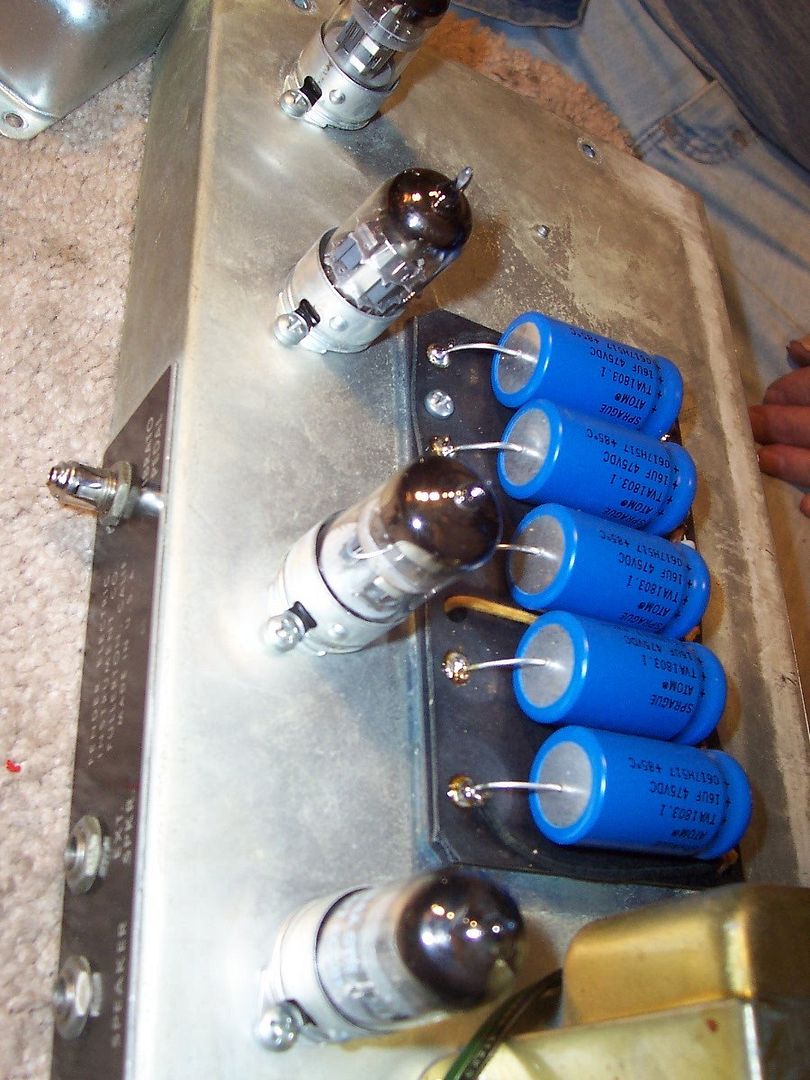
Here's a bit of Fender trivia: All the caps in that photo have the same polarity — therefore, it's probably a Deluxe Reverb or Vibrolux Reverb amp. In this case, it's a DR. Most 6V6GT Fender amps used cap cans.

Nearly all of the big boy 6L6GC amps had the first two caps reversed. MANY blown recap jobs were due to inattentive technicians. :)


3a8460c9-934e-4ec0-b1b1-7dcf9e51a1dc.jpg

Bassman caps.

19b7b4e5-e9ab-40fa-ad06-28414ce46510.jpg

Super Reverb.
 
Last edited:
Here's a bit of Fender trivia: All the caps in that photo have the same polarity — therefore, it's probably a Deluxe Reverb or Vibrolux Reverb amp. In this case, it's a DR. Most 6V6GT Fender amps used cap cans.

Nearly all of the big boy 6L6GC amps had the first two caps reversed. MANY blown recap jobs were due to inattentive technicians. :)


3a8460c9-934e-4ec0-b1b1-7dcf9e51a1dc.jpg

Bassman caps.

19b7b4e5-e9ab-40fa-ad06-28414ce46510.jpg

Super Reverb.
I knew that. I thought DR after I typed….reason I figured possibly Princeton was smallish output transformer.
 
I learned something new today, thank you! With the split load phase inverter, and multi section can cap, you would think it was a mono hifi amp.
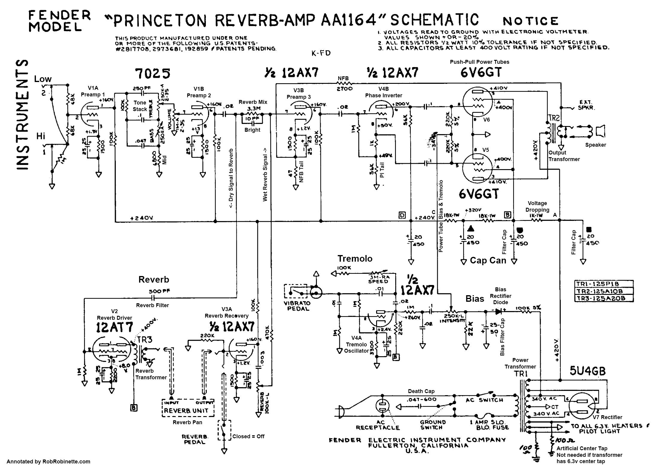
Those Blackface and Silverface era Princeton Reverb amps used the other half of the 12AX7 as the Tremolo (Vibrato) driver. Click on the image to enlarge it.

AA1164_Princeton_Reverb_Annotated_Schematic.png
 
Those Blackface and Silverface era Princeton Reverb amps used the other half of the 12AX7 as the Tremolo (Vibrato) driver. Click on the image to enlarge it.

AA1164_Princeton_Reverb_Annotated_Schematic.png
The “bias wiggle” tremolo; I tried that circuit on a Vibroverb clone. I didn’t see any benefit, but the guy that bought it seemed to like it. It did seem to overdrive different, probably because no 50K load of the optocoupler type. I think that I went considerably higher value, don’t recall.
 
The “bias wiggle” tremolo; I tried that circuit on a Vibroverb clone. I didn’t see any benefit, but the guy that bought it seemed to like it. It did seem to overdrive different, probably because no 50K load of the optocoupler type. I think that I went considerably higher value, don’t recall.
I like Princeton's bias waggle tremolo. It's a bit smoother than the amps with the optocoupler bugs.

The best tremolos are the tube-driven oscillators. Those amps can require two or even three extra 12AX7 tubes, so they fell out of favor from manufacturers due to the extra chassis space taken and the cost. However, the tone of these amps is so tubular! :)

10120227-1cc9-4f4e-9502-bbe8a8aa3156.jpg

My 1992 Fender Pro amp and Reverb units.


434013c1-19c9-4082-a16f-9b336c65150a.jpg

Click on the image to enlarge.
 
I like Princeton's bias waggle tremolo. It's a bit smoother than the amps with the optocoupler bugs.

The best tremolos are the tube-driven oscillators. Those amps can require two or even three extra 12AX7 tubes, so they fell out of favor from manufacturers due to the extra chassis space taken and the cost. However, the tone of these amps is so tubular! :)

10120227-1cc9-4f4e-9502-bbe8a8aa3156.jpg

My 1992 Fender Pro amp and Reverb units.


434013c1-19c9-4082-a16f-9b336c65150a.jpg

Click on the image to enlarge.
I have replaced the master volume with that variable feedback “presence “ circuit on a couple of late silver face Twins….
 
Back
Top Bottom