• The move to the new server is done. There are some software and database maintenance updates in process. This has us passing the hat around to help out. We appreciate any donations. Seriously, even a dollar helps. The payment page may be found here - https://www.audiokarma.org/support.html

Fisher 800C Restoration Process.

cyclop

New Member
I’ll be starting the restoration of my Fisher 800-C and plan to take it one step at a time, starting with the power supply.

My initial steps will be replacing the Siemens selenium bridge rectifier with a modern silicon bridge, checking/replacing the main electrolytic capacitors, and then carefully checking the power supply voltages before proceeding further.

I’m using GE 7591A output tubes, and I’m a little concerned about the higher B+ voltage that can result from replacing the selenium rectifier with silicon.

A couple of questions for the group:

  • What additional steps should I take after replacing the selenium bridge with a silicon rectifier?
  • Should I add a dropping resistor or otherwise adjust the B+ voltage?
  • Is there any real benefit to using 2200 µF capacitors in the power supply, or is that unnecessarily large for the 800-C?
My next major step will be installing IBAM, but I’d really like to get the receiver safely up and running first. I want to enjoy it for a while before I take on the IBAM board and the rest of the updates.

Any advice on the safest way to bring this 800-C back online would be greatly appreciated!
 
Register to hide this ad
Here is my 2014 experience with my 800c restoration

 
The bridge rectifier should be directly replaced with an appropriate silicon piece. No circuit adjustments are necessary — Fisher made no adjustments when they converted their receiver line to silicon in the latter days of producing those units. A silicon bridge rectifier can raise the B+ slightly due to providing more bias voltage to the output tubes. That is a good thing however as it helps to maintain the designated output tube current draw with today’s higher line voltages. Use a CL-80 current limiter in a primary lead to the power transformer, and all voltages will be fine — no additional B+ dropping resistor is necessary. Additional capacitance in the DC Heater-Bias supply will aid filtering somewhat, but the original values get the job done adequately just fine.

I hope this helps!

Dave
 
So, I started the restoration process by replacing the light bulbs and cleaning the front glass, which had all kinds of grime on it, including nicotine. In the process, I removed all the knobs.

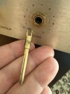
Unfortunately, the volume control shaft, which had been problematic before, came completely out. It looks like whoever serviced it previously used crazy glue on the tip to secure it, as there was glue residue at the end.

At this point, I’m not sure which direction I should take. Should I try the replacement volume control from Reverb, or should I try to fabricate one based on the design described in this thread?
Has anyone tried making one of these as per those instructions?
Volume.jpg
 
Back
Top Bottom