• The move to the new server is done. There are some software and database maintenance updates in process. This has us passing the hat around to help out. We appreciate any donations. Seriously, even a dollar helps. The payment page may be found here - https://www.audiokarma.org/support.html

Fisher Coronet Modern

FireGuruMN

Active Member
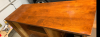
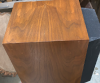
Oh no, another console! The woodwork on this one is in pretty rough shape. Missing the legs and lots of watermarks. But the previous owner used it as their daily music source! Apparently the "balance" had to be mostly to one side to get it to sound good.
The front view:
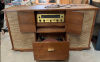
upload_2019-9-5_16-16-7.png
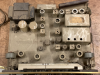
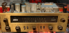
The Chassis (100T I believe):
upload_2019-9-5_16-17-32.png
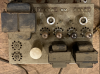
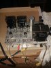
The amplifier (SA-16)
upload_2019-9-5_16-18-20.png
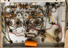
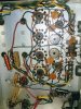
The insides of the amplifier:
upload_2019-9-5_16-19-1.png
Where to start? First I want to get the outside work done before the winter sets in. Does anyone have dimensions or a pattern or a good picture of the legs? I found this but it is in a 3D sketch and not much good for determining dimensions. Are the legs slanted outward AND cut at an angle inside?
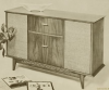
upload_2019-9-5_16-21-39.png
It will be hard to find a matching vase to sit on top also. :)
Notice that there are no rectifier tubes on the amplifier. There are diodes installed and the heater wires have been cut. Other pictures I see from the internet show a capacitor installed in there also. The wiring lug for the cap does not appear to have ever been soldered. So was this a factory modification. Not in 1961 if my electronics history tells me anything. There is also a socket behind the can capacitor that never appear to have been soldered. I probably want to switch this back to tube rectification and all. I found a picture of one for sale and it looks like they put a switch in the socket by the capacitor. So what was that ever used for?

I have everything cleaned up. I used some "LA's totally awesome cleaner" from the Dollar Store. It lives up to its name. I saw it recommended on a youtube video. This is the first time I tried it out. It dissolved all the gunk and left the lettering intact. I blew the loosened gunk out with an air compressor and let it dry. Almost painless.

I ordered new caps and tubes (except for rectifiers) for the amp. The existing ones were not good and I am surprised they were even making music at all. The original Fisher 12ax7's were good. Some of the lettering was missing from the amp before I started. I might end up painting the amp chassis since the lettering is in bad shape and the raw metal is not the prettiest. I have not gone through the preamp yet. I'm distracted by a ST70/FM3/SCA-35 that I reeled in. Original Dyanco power tubes and all!

oh, the speakers work but are dull because of the old capacitors. I have not tried the turntable. There is no spindle. . .
 
Register to hide this ad
More pics. Everyone loves pics.
Nice condition on the face:
upload_2019-9-5_16-43-21.png
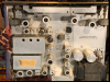
Cleaned up very nice inside:
upload_2019-9-5_16-43-54.png
Missing some lettering. I think there were mice down there at some point:
upload_2019-9-5_16-45-22.png
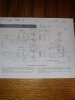
I do have the schematics but the socket by the large capacitor is still a mystery. No soldering on it ever that I can see.
 
The legs are straight with a bevel cut on the inner side, about 7" length. The socket next to the Large capacitor is most likely the "SHORTING PLUG" for a wired remote (see SA-16 Schematic upper right corner) for stand-alone use. The SA-16 has TWO(2) rectifiers (EZ-81/6ca7) which would be in the lower right corner of your picture. IIRC the 100-T has a plug that connects there, but not totally sure.

EDIT!: The manual is incorrect for the LOWER RECTIFIER TUBE(V-8) on the SA-16. The correct Tube # is EZ-81/6CA4
 
Last edited:
I think the manual I just found is to large to attach. Can be found on Fisher website.
 
Last edited:
The 100T is a stand alone device requiring no slave power to operate. It contains it's own power supply for all its onboard needs and can operate stand alone as built.

The 7 pin socket on the SA-16 requires that either that the plug on the umbilical cord from one of Fisher's typical tuner/pres that requires the power amp power supply to power it be plugged into it -- or -- the shorting plug be plugged into it.

In the first scenario, there is only one AC power cord (that being the SA-16s), with the switch controlling power to it, and the power necessary to operate the tuner/pre all being connected through the 7 pin plug.

In the second scenario, if the shorting plug is not available, pins 1&2 need to be shorted together, which then completes the AC power to the SA-17. But also, pins 5&6 need to be shorted together as well, which then connects R33 into the circuit (which is normally connected to nothing). This resistor takes the place of the preamp tube heaters that would normally be connect into the cathode circuit of the output tubes when the SA-16 is powering a tuner/pre that requires external power to operate.

If the SA-16 is to be operated in stand alone fashion, then either the shorting plug is necessary, or, the appropriate pins shorted together as indicated above. If neither of these things are done, then the SA-16 will be dead as a door-nail if stand alone operation is attempted.

The SS rectifier modification is clearly non-factory work. The modification could have been done as early as 1960, as decent silicon diodes were available that year (i.e.,1A@400 volt PIV) -- but it would have required two to be connected in series on each side of the full wave design. Since that is not what was done, the modification was done well after the unit was built.

The 6CA4 is a low drop rectifier, so the voltages are going to be higher than normal -- but not nearly as high as when SS rectifiers are used to replace (say) a 5U4GB high drop rectifier. If you elect to keep them in, you will want to make sure that the turn on surge voltage (before the output tubes warm up) of the main B+ point does not exceed about 400 vdc (which it likely will), unless the voltage rating of at least C12C, C12D, and C13 are increased, as this is the surge voltage limit of the stock caps installed at these points. The voltage ratings of C12A and C12B should be increased as well for good measure if the SS rectifiers remain.

Good luck with your console!

Dave
 
Last edited:
Recently aquired one of these console's. Bringing it up on a variac A channel sounds fine, the B channel has alot of distortion. I did clean pots, sockets and swapped tubes from one channel to the other. I will recap this amp but was curious if a lower value C11 cap would cause this. Looking at the schematic for the SA16 and comparing capacitors they call a 100uf 100v cap for part number C11. In the amp it has a 50uf 25v in that place. This amp does not have the shorting plug.
View attachment 1611264 View attachment 1611281

View attachment 1611264
I found a thread yesterday that Larry included a link for a F220 manual and schematic and can not find it now. It was slightly different as it's parts list included R36 and R37. Also seen Dave's advice on having a closely matched power tubes. Not sure on the ones I'm using right now. Any chance of reposting that link. I thank you if can help out.
 

Attachments

  • 15678181969051679441058.jpg
    15678181969051679441058.jpg
    50.4 KB · Views: 34
  • 15678182270651603765270.jpg
    15678182270651603765270.jpg
    35.8 KB · Views: 31
  • 20190823_221658~3.jpg
    20190823_221658~3.jpg
    92.2 KB · Views: 31
  • 20190905_174007.jpg
    20190905_174007.jpg
    61.9 KB · Views: 32
We all know Fisher certainly had their share of schematic errors -- and that's another......

Dave
 
Thanks Larry for your quick response but I mistakenly posted the the wrong model number (F220 wrongo). I'm actually looking for the 2 different Coronet console manuals you posted a while back. I do have the C 55 manual but there is another one you had a link to. They both use the SA 16 power amp and the 100T tuner preamp. They have a slightly different schematic. Thanks again to you, Dave and all the others who help us novice rebuilders understand the in's and out's of these fantastic pieces of audio history.
 
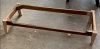
Working on the new legs:
upload_2019-9-8_9-38-56.png
Before glue so it's a little wonky on the floor:
upload_2019-9-8_9-39-53.png
I used oak and made them a little thicker than the originals. My daughter says she can stain anything to look like anything so we will see. I still need to round the edges a bit to match to other edges on the base frame.

On the electronic side:
Much to my terror I put the original Fisher 12ax7's in my tester and the heaters burned out in a bright glow. Something has gone wrong with my tester! It's putting 90vac out on the heater pins! Time to find a new tester. So off to the internet to order rectifier tubes and 12ax7's. What is left of the screening on my amp shows 6CA4's in both rectifier positions so I going that way. I did see the other tube type on the schematic though. Interesting.
I ordered Solen caps to replace C7,8,9,10 and a couple of others also. I like the sound and look of those caps. This is the first amp I have seen using disc caps on output tubes. I ordered a 450v version of the C12 can multi-cap. I will be adding a CL80 thermistor or two also on the input power. I still have to order safety caps and a couple of other bits. The comments about excessive startup voltages could explain the "popping" that the previous owner heard when starting this up. Still scary that this was used daily in this condition. I'm going to go through the schematic and compare to my unit point by point when I rewire it to use rectifier tubes.

But the outdoor work is moving along. Today I sand the water stains out of the top. They go pretty deep.
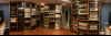
Check out the shelves I built earlier this summer:
upload_2019-9-8_10-4-48.png
The difference between hoarding and collecting is nice shelves. :rflmao:. And they even act as a pretty good bass trap so the room sounds better.
Thanks for all the replies.
 
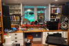
That is my workroom/listening room. Here is the bench side. I don't have all the scopes and such installed yet. That's a winter project. But it has one thing most workrooms I have seen do not have, a window!
upload_2019-9-9_17-32-56.png

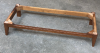
Here is the base all finished up:
upload_2019-9-9_17-32-1.png
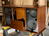
Here is how the cabinet is looking. I think this is darker than the original stain but I just refinished the top and left the rest how I found it. I used red oak stain on whatever wood that is. Walnut? It looks great according to quality control (wife).
upload_2019-9-9_17-36-58.png
 
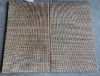
Here are the speaker grills before (left) and after (right). I used full-on bleach and scrubbing to get the smoke stains out of them. As near as I can determine they are plastic. I don't know if that is original. I think my other console had actual organic material in the grills. The brass handles that give this much of the mid-century modern feel cleaned up nicely also (no picture).
upload_2019-9-9_17-41-50.png
Maybe this should all go on "woodkarma" instead but here you are. Amplifier bits should be here soon.
 
Nice work on the Coronet so far. Looks great! The SA-16 has really been overlooked in Fishers’s canon and doesn’t get anywhere the love that it’s fixed bias brother the SA100 gets. It’s a very simple circuit but has great output transformers. Upgrading the caps to something better than the ceramic discs will up the ante substantially and then it basically comes down to tubes. Unless you plan on seriously altering the circuit, all 4 power tubes (7189, not EL84) share a common cathode resister and need to be well matched for current draw. Your options will be limited to Russian 6N14N-EB or Sovtek El84M for new properly matched tubes unless you want to search hard and pay dearly for real 7189’s. Good luck and enjoy!
 
I have a set of EL84M's in my SA100 and I ordered a matched quad of EL84 Electro Harmonix from AES for this project. I might swap them around but I do like the sound of the Electro's. I have a set of Electro in a Heathkit AA-100 and I love the blue/purple glow they put out (as well as the sound). So I though I would give them a try here.

I put a third coat of poly on the top of the console tonight. Sorry all of those folks that hate poly but this one had already had some and I did not want to strip it all off. I managed to sand almost all of the water stains out of the top. I had to leave in a couple of cigarette burns that went down to the bone.
upload_2019-9-10_21-1-58.png
And one set of cat claw marks most of the way across the top that went very deep. Must have been a big cat!
upload_2019-9-10_21-3-26.png
I re-oiled a pair of KEF 104/2's today also. I am totally amazed at the veneer on those. It is book matched front to back and continuous grain all the way around the entire speaker. I wonder if anyone else notices these things. I did continuous grain around a couple of receiver cases so I know how hard that is to do. The rest of the KEF project will be another thread.
upload_2019-9-10_21-4-13.png
 
The Electro Harmonix EL84’s may not live long in the SA-16. Even with the (somewhat) controlled warmup of the indirectly heated 6CA4 rectifiers, the power tubes see a spike of grid voltage in these amps on turn-on that will light up the screens long before the filaments have time to heat the cathodes. Plate voltage hits in maybe 10-15 seconds. Go as robust as you can on power tubes and/or ramp up voltage with a variac every time you turn on. Install a thermsistor or use a bucking transformer to get your wall voltage below 117v.
 
I concur with Kevco on getting as Robust a tube as you can for the SA-16. Fisher ran their amps hard, and even 7189's are run near or at the ragged edge of the envelope. Stick with the EL-84M's or the 6N14N-EB for this one.
 
Got it. I will use the EL84M's in this amp instead of the new EL84's. I run all my tube amps on a bucking transformer setup. And they all get thermistors. Hmm, maybe I should put a thermistor in with my bucking transformer also. I like that idea.

Anything special I should do with the speakers other than replace the capacitors?
upload_2019-9-11_7-17-45.png
 
Back
Top Bottom