You are using an out of date browser. It may not display this or other websites correctly.
You should upgrade or use an alternative browser.
You should upgrade or use an alternative browser.


FireGuruMN
Active Member
Finished with the cabinet:

The new legs are more "grainy" than I would like but at least they exist now.
I think the same cat that put scratches in the top also used the speaker grills as a scratching post. They look ok but someday I might replace the grills if I can find something that matches the original well.
The perils of doing wood finishing in the garage:
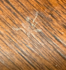
At least there is one less mosquito in Minnesota. . .
Still waiting for some electronic bits to show up for the amplifier restoration.
The new legs are more "grainy" than I would like but at least they exist now.
I think the same cat that put scratches in the top also used the speaker grills as a scratching post. They look ok but someday I might replace the grills if I can find something that matches the original well.
The perils of doing wood finishing in the garage:
At least there is one less mosquito in Minnesota. . .
Still waiting for some electronic bits to show up for the amplifier restoration.

Finished with the cabinet:
View attachment 1616591
The new legs are more "grainy" than I would like but at least they exist now.
I think the same cat that put scratches in the top also used the speaker grills as a scratching post. They look ok but someday I might replace the grills if I can find something that matches the original well.
The perils of doing wood finishing in the garage:
View attachment 1616592
At least there is one less mosquito in Minnesota. . .
Still waiting for some electronic bits to show up for the amplifier restoration.
Looking very good. The feel turned out very nice.

Nice job on the cab 

FireGuruMN
Active Member
Well Winter is back and I am on the bench again. I think I am ready to power up the SA16 now. Here is what it looks like:
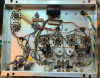
Please don't look too closely!
Here is what I did:
Anyone see anything obviously wrong?
A few questions:
What is that terminal strip above the diode tubes for?
How do I bias this thing? The manual says some magic about distortion measurement. That was all Chinese algebra to me. I saw some picture with precision resistors added for bias measurements. Should I go there?
Please don't look too closely!
Here is what I did:
- Removed the SS diodes and rewired that bases for tubes.
- Reinstalled the heater wires to the tubes.
- The resistors on the terminal strip for the heaters were wide open and toasted. I replace them. 220 ohms is what my brain gave me for a value reading the colors.
- I replaced the death capacitor with an XY safety cap.
- Added a CL80 thermistor to the power input.
- Replace 6 of the .02uf ceramic caps with .022uf Solen caps (1000 volts rating is excessive but that is what is out there.)
- Replace the 100uf cap. (Again 500v rating is excessive but that is what was on the website I ordered tubes from)
- Replaced the can capacitor.
- Replaced the 22kohm resistors on the can cap because it was easier than resoldering them.
Anyone see anything obviously wrong?
A few questions:
What is that terminal strip above the diode tubes for?
How do I bias this thing? The manual says some magic about distortion measurement. That was all Chinese algebra to me. I saw some picture with precision resistors added for bias measurements. Should I go there?
FireGuruMN
Active Member
Oh, and there was black goo oozing out of the old can cap. How on earth was this thing playing music? Out of curiosity I measured the capacitance and all the values read good. YES, I know that is meaningless. There were obvious signs of huge ESR values inside the can. The can was actually bulging and had a tan color from excessive heat.
Last edited:
FireGuruMN
Active Member
Finally got around to powering up the SA16. No surprises. Played it for a while and it sounds great. Here is the top with all the tubes installed:
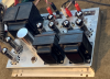
I read the manual about how to adjust the pots on the top. Apparently it requires a signal generator and distortion analyzer. "set the pots to minimum distortion". There is no distortion analyzer on my bench so is there some other process I could use? Could I hook up a scope and make the sine wave look nice at the crossover point? Right now I just centered them. is there a better place to put them without taking any measurements?
anyone have a process for replacing the lettering on the chassis that is gone? My best plan is a label printer with clear sticky labels. Might be better to do nothing at that point?
I used all Electro-Harmonix matched output tubes and EH for everything else also. Played it for an hour or so and no red plating or smoke. Onward to the Preamp/Tuner. When the outdoors thaws I will put it all in the console, recap the speakers and head back to the 60's.
I read the manual about how to adjust the pots on the top. Apparently it requires a signal generator and distortion analyzer. "set the pots to minimum distortion". There is no distortion analyzer on my bench so is there some other process I could use? Could I hook up a scope and make the sine wave look nice at the crossover point? Right now I just centered them. is there a better place to put them without taking any measurements?
anyone have a process for replacing the lettering on the chassis that is gone? My best plan is a label printer with clear sticky labels. Might be better to do nothing at that point?
I used all Electro-Harmonix matched output tubes and EH for everything else also. Played it for an hour or so and no red plating or smoke. Onward to the Preamp/Tuner. When the outdoors thaws I will put it all in the console, recap the speakers and head back to the 60's.

fred soop
Super Member
You could use a scope. There is a test for solid state amplifiers that might be of help with a tube amp. Use a 10 kHz sine wave at 1 watt (2 V rms or 2.83 V peak) into a 4 Ω load and observe. One circuit that I tested had very obvious crossover distortion that was easily tuned out by increasing bias.
Finally got around to powering up the SA16. No surprises.......
......anyone have a process for replacing the lettering on the chassis that is gone? My best plan is a label printer with clear sticky labels. Might be better to do nothing at that point?
.
The label printer will work. If you want a more accurate representation of what was there, water slide decals is the way to go. A much more intensive process requiring identifying and sizing the characters, doing the computer work, and then setting them up on the chassis with all the proper materials. If you're not concerned with appearance and care only about identification, then the label printer is much, much easier. A stop at the video site will clue you into what's involved.
Below is my son's work for my SA-100. Nice but so much work to final product.