

You are using an out of date browser. It may not display this or other websites correctly.
You should upgrade or use an alternative browser.
You should upgrade or use an alternative browser.
Fisher KX-100 (X-100-B) Output Transformer source
- Thread starter richiem46
- Start date


I was thinking about the transformer situation and decided to go back out to the garage briefly and open up the good transformer of the pair I replaced with the Transendars last year. Here is a picture of it. It looks like it has seen some heat bur isn't oozing "stuff" out of the windings so I am assuming it is usable. Will check resistance measurements but if I remember correctly it measured consistent with other measurements published by Dave and others pursuing transformer issues on the KX-100 on Audiokarma.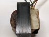
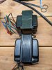
An update to my transformer search. I received the two Fender Original Hot Rod Deluxe transformers the other day. They are direct physical replacements for the Fisher units and I am attaching a picture of the Fender unit and an original Fisher transformer here for reference.
I have been doing some research and here are my thoughts to date on installing the Fender transformers:
The Fender Original Hot Rod Deluxe and Blues Deluxe output transformer specifications that I am using as a temporary replacement in the KX-100 are listed below:
Specifications
Audio Power
40 W (RMS)
Primary Impedance
4,250 Ω
Secondary Impedance
4/8 Ω
Mounting Centers
2" x 2.2"
Mounting Type
Vertical
Weight
3.4 lbs
I calculated the impedance ratio using the transformer specifications above. For the 8 ohm tap 4,250/8 = 531.25. For the 4 ohm tap 4250/4 = 1,062.5.
The 7868 specifies a plate impedance of 6,600 so for the 8 ohm tap on the Fender transformer 6,600/531.25 = 12.4 ohm implying the 8 ohm tap in this configuration has an impedance of 12.4 ohms. For the 4 ohm tap 6,600/1,062.5 = 6.2 so the 4 ohm tap in this configuration has an impedance of 6.2 ohms. I plan to use the 4 ohm tap (6.2 ohms) with an 8 ohm speaker as that is the closest match. Not optimal but it should make the amp usable in the interim until I can secure a more suitable replacement. The edcor’s are much more $$ and the leads for the primary and secondary are on opposite sides of the bell housing which complicates the physical installation and the mounting holes also require accommodation. (and they are Blue….). I can see why others have used the Fender transformers as an interim solution as they present no mechanical installation issues.
I am a bit concerned with how the Fender installation will affect the negative feedback loop. Fisher’s grounding the 4 ohm tap and using the ground lead for feedback is kind of interesting. The R51/C19 and R52/C30 1.8K/630PF appear to determine the amount of negative feedback to the phase inverter stage. I am assuming that the level of feedback will be higher with the new transformer as the impedance of the 4 ohm tap is effectively 6.2 ohms now. The 630PF bypasses the 1.8K series resistor for higher frequencies I am guessing, perhaps to protect against potential feedback? I lot of guessing/surmising on my part, am I over thinking this and should I just leave the feedback network as is or modify it in some way to compensate for the Fender transformers?
Thanks for any thoughts or feedback anyone may have.......
Rich
I have been doing some research and here are my thoughts to date on installing the Fender transformers:
The Fender Original Hot Rod Deluxe and Blues Deluxe output transformer specifications that I am using as a temporary replacement in the KX-100 are listed below:
Specifications
Audio Power
40 W (RMS)
Primary Impedance
4,250 Ω
Secondary Impedance
4/8 Ω
Mounting Centers
2" x 2.2"
Mounting Type
Vertical
Weight
3.4 lbs
I calculated the impedance ratio using the transformer specifications above. For the 8 ohm tap 4,250/8 = 531.25. For the 4 ohm tap 4250/4 = 1,062.5.
The 7868 specifies a plate impedance of 6,600 so for the 8 ohm tap on the Fender transformer 6,600/531.25 = 12.4 ohm implying the 8 ohm tap in this configuration has an impedance of 12.4 ohms. For the 4 ohm tap 6,600/1,062.5 = 6.2 so the 4 ohm tap in this configuration has an impedance of 6.2 ohms. I plan to use the 4 ohm tap (6.2 ohms) with an 8 ohm speaker as that is the closest match. Not optimal but it should make the amp usable in the interim until I can secure a more suitable replacement. The edcor’s are much more $$ and the leads for the primary and secondary are on opposite sides of the bell housing which complicates the physical installation and the mounting holes also require accommodation. (and they are Blue….). I can see why others have used the Fender transformers as an interim solution as they present no mechanical installation issues.
I am a bit concerned with how the Fender installation will affect the negative feedback loop. Fisher’s grounding the 4 ohm tap and using the ground lead for feedback is kind of interesting. The R51/C19 and R52/C30 1.8K/630PF appear to determine the amount of negative feedback to the phase inverter stage. I am assuming that the level of feedback will be higher with the new transformer as the impedance of the 4 ohm tap is effectively 6.2 ohms now. The 630PF bypasses the 1.8K series resistor for higher frequencies I am guessing, perhaps to protect against potential feedback? I lot of guessing/surmising on my part, am I over thinking this and should I just leave the feedback network as is or modify it in some way to compensate for the Fender transformers?
Thanks for any thoughts or feedback anyone may have.......
Rich

Rich -- using the 4Ω tap for an 8Ω load would be the way to go -- reflecting 8500Ω back to the tubes. In the later version 400 receivers, Fisher used a 10KΩ primary impedance, so that value is not unrealistic.
The 4Ω tap was grounded so as to allow for a powered center speaker connection. With the 4Ω tap also being the CT of a 16Ω winding, by grounding it and then attaching the center speaker to the 16Ω output of one channel, and the Common of the other, the center speaker then received a true L+R signal of equal amplitude from the two amplifiers -- but it required the two amplifiers to have their 4Ω taps grounded. With the replacement transformers, by using the 4Ω taps as 8Ω outputs, the NFB level will effectively be increased, so the lower ladder resistor of the NFB network (where the NFB network connects) to will need to be reduced to maintain the same FB level. For lack of anything better, replace the existing value with one equal 70.7% of the original value.
This is only a rough guess, as working against this approach is the fact that the primary impedance is also now effectively higher than the original value, so to some degree, the two effects are working to cancel each other out.
Two other issues to address:
1. There's no guarantee that the primary wire color code matches that of the original transformer -- nor does the secondary for that matter. If the amplifier oscillates when powered up, switch the plate leads to the output tubes.
2. For best performance, run a 10 kHz square wave through the power amplifier section proper (if possible), and adjust the cap in the NFB network for best waveform (least ringing with little or minimal overshoot).
Good luck with it!
Dave
The 4Ω tap was grounded so as to allow for a powered center speaker connection. With the 4Ω tap also being the CT of a 16Ω winding, by grounding it and then attaching the center speaker to the 16Ω output of one channel, and the Common of the other, the center speaker then received a true L+R signal of equal amplitude from the two amplifiers -- but it required the two amplifiers to have their 4Ω taps grounded. With the replacement transformers, by using the 4Ω taps as 8Ω outputs, the NFB level will effectively be increased, so the lower ladder resistor of the NFB network (where the NFB network connects) to will need to be reduced to maintain the same FB level. For lack of anything better, replace the existing value with one equal 70.7% of the original value.
This is only a rough guess, as working against this approach is the fact that the primary impedance is also now effectively higher than the original value, so to some degree, the two effects are working to cancel each other out.
Two other issues to address:
1. There's no guarantee that the primary wire color code matches that of the original transformer -- nor does the secondary for that matter. If the amplifier oscillates when powered up, switch the plate leads to the output tubes.
2. For best performance, run a 10 kHz square wave through the power amplifier section proper (if possible), and adjust the cap in the NFB network for best waveform (least ringing with little or minimal overshoot).
Good luck with it!
Dave
Dave,
I appreciate your insight into the 4 ohm ground on the Fisher speaker outputs. I always scratched my head about the arrangement Fisher used but your explanation clarified things for me. I plan on replacing both output transformers with the Fender units as both outputs were bad (lucky me!) and will wire both channels symmetrically so I should avoid potential oscillation in theory. Based on your recommendation I will substitute a 1.4K resistor for R51/52 for my initial testing.
I ordered replacement filter Caps from Hayseed Hamfest and their production is affected by component delays. I plan on performing your Zener diode modification and also installing individual bias controls for the four outputs and the 10 ohm cathode and 100 ohm screen resistors. BTW I have performed these mods on several KX-100’s to good effect and given the transformer changes I am making feel it is best to perform them all before performing any initial testing.
We are getting ready to head to Florida for the winter next week from Michigan so I will complete all the restoration work there when the filter caps arrive. Once the amp is initially working I will break out the signal generator and scope and fiddle with the NFB cap to get the best result with the 10 khz square wave. I will post a progress report in 2-3 weeks once we get settled in down south.
Thanks for your assistance and encouragement!
Rich
I appreciate your insight into the 4 ohm ground on the Fisher speaker outputs. I always scratched my head about the arrangement Fisher used but your explanation clarified things for me. I plan on replacing both output transformers with the Fender units as both outputs were bad (lucky me!) and will wire both channels symmetrically so I should avoid potential oscillation in theory. Based on your recommendation I will substitute a 1.4K resistor for R51/52 for my initial testing.
I ordered replacement filter Caps from Hayseed Hamfest and their production is affected by component delays. I plan on performing your Zener diode modification and also installing individual bias controls for the four outputs and the 10 ohm cathode and 100 ohm screen resistors. BTW I have performed these mods on several KX-100’s to good effect and given the transformer changes I am making feel it is best to perform them all before performing any initial testing.
We are getting ready to head to Florida for the winter next week from Michigan so I will complete all the restoration work there when the filter caps arrive. Once the amp is initially working I will break out the signal generator and scope and fiddle with the NFB cap to get the best result with the 10 khz square wave. I will post a progress report in 2-3 weeks once we get settled in down south.
Thanks for your assistance and encouragement!
Rich
Rich -- The resistor you would be changing would be the lower resistor in the NFB "ladder", which is the 220Ω resistor in the cathode circuit of the driver tube. However, I see that changing that resistor would also change the positive feedback from the inverter stage in such a way to lower open loop gain -- which would detract from, performance. Therefore, it would be best in this instance then to take the existing NFB resistor -- 1.8K -- and divide it by the same 70.7%, which would suggest a new value for the NFB resistor would be 2546Ω. The closest normal production value then would be to change the NFB resistors to 2.7K from their current 1.8K when installing the new transformers. The 220Ω resistors I was originally targeting for change would remain the same. Because the NFB resistor is changing however, the cap across the FB resistor should be reduced to the closest production value of 450 pF, to compensate for the larger FB resistor value being used.
Dave
Dave
Dave,
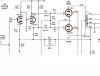
Funny, after I sent my reply I was thinking that reducing the R51/R52 value to reduce the negative feedback seemed counter-intuitive and realized I was confused by the nomenclature. The resistor to ground (220 Ohm) is referred to as the “shunt” resistor in the materials I came across rather than the “lower-ladder” resistor. I should have included a snippet of the KX-100 schematic in my post so we had a common reference point. As you observed, the 220 ohm resistor is part of the cathode circuit and should be left alone. I will make the changes to the R51/C29 network in both channels that you suggested when I do the restore in Sunny Florida and do the testing with that configuration. Sorry for the confusion!
Rich
Well we made it to Florida with all my electronic gear and other misc. stuff and are settled in. I started working on the amplifier again and installed the screen stability resistors and the 10 ohm cathode resistors. I replaced the power supply caps with the Hayseed Hamfest caps, replaced the rectifiers and installed the Fender output transformers. I also replaced the 5 amp fuse the previous owner had installed (no wonder the outputs blew!) with a 2 amp fuse. I then attached speakers to the 4 ohm terminals (using 6 ohm bookshelf units which are a good match with the new transformers) .
I then attached a music source to the aux inputs and plugged the amp in and GRADUALLY increased the AC voltage while monitoring the Plate side of the HV supply. When the plate voltage reached about 320v the amp started to make some very interesting and kind of frightening noises. It sounded like a cross between a fog horn and a very loud bullfrog. I immediately powered the amp off and pondered what was going on. I went back and re-read this thread remembering something Dave had said about oscillating and reversing the plate leads should it occur.
I re-wired the plate sides of the transformers (fortunately I had saved the pieces of the leads I had trimmed off). A bit of solder, some heat shrink tubing and I was ready to try again. I gradually powered the amp up again and..........It worked!!!!!!!
Now I know what an oscillating Amp sounds like! Thanks to Dave for saving me a lot of PD with his suggestion on swapping the plate leads. I would have never thought to do that.....
I did some quick voltage measurements at 115VAC and the plate was OK but the screens were at 285V, kind of low. Lot of voltage drop across the 2.5K power resistor. Th cathode resistors indicated that the 7868's were quite out of balance and operating way too hot. I had been using them in an KX-100 that I had added individual bias pots to so that is the next item on the to-do list along with the inrush inhibitor and the zener diode modification. I am hoping balancing the 7868's will settle down the Screen voltage and the cathode draw with the new transformers.
It is early in the restoration but I have to say the amp sounded surprisingly good in it's present state. After the modifications to the bias network I will replace all the old brown coupling caps and modify the NFB as discussed above and then break out the scope to see how things are going. I am attaching a picture of the final wiring of the outputs for reference.
Will post more as things progress.
Rich
I then attached a music source to the aux inputs and plugged the amp in and GRADUALLY increased the AC voltage while monitoring the Plate side of the HV supply. When the plate voltage reached about 320v the amp started to make some very interesting and kind of frightening noises. It sounded like a cross between a fog horn and a very loud bullfrog. I immediately powered the amp off and pondered what was going on. I went back and re-read this thread remembering something Dave had said about oscillating and reversing the plate leads should it occur.
I re-wired the plate sides of the transformers (fortunately I had saved the pieces of the leads I had trimmed off). A bit of solder, some heat shrink tubing and I was ready to try again. I gradually powered the amp up again and..........It worked!!!!!!!
Now I know what an oscillating Amp sounds like! Thanks to Dave for saving me a lot of PD with his suggestion on swapping the plate leads. I would have never thought to do that.....
I did some quick voltage measurements at 115VAC and the plate was OK but the screens were at 285V, kind of low. Lot of voltage drop across the 2.5K power resistor. Th cathode resistors indicated that the 7868's were quite out of balance and operating way too hot. I had been using them in an KX-100 that I had added individual bias pots to so that is the next item on the to-do list along with the inrush inhibitor and the zener diode modification. I am hoping balancing the 7868's will settle down the Screen voltage and the cathode draw with the new transformers.
It is early in the restoration but I have to say the amp sounded surprisingly good in it's present state. After the modifications to the bias network I will replace all the old brown coupling caps and modify the NFB as discussed above and then break out the scope to see how things are going. I am attaching a picture of the final wiring of the outputs for reference.
Will post more as things progress.
Rich
I have now completed my restoration on the KX-100. To summarize, I replaced all the signal path caps with IC Mylar units. The filter caps were replaced with Hayseed Hamfest replacements, the power supply diodes were replaced with modern units. The 2500 ohm power resistor R72 was replaced with a 2700 ohm unit to lower the screen and other voltages a bit with modern 120VAC line voltage. An inrush inhibitor was also installed in the AC line.
I replaced R71 with Dave’s Zener diode mod and replaced C4 with a 200MF 300V unit which I had on hand. I read (somewhere) that increasing the size of the cathode capacitor would reduce the cathode voltage variation a bit, providing a more stable bias voltage. Not sure if this is true but figured it wouldn’t hurt. The 10-ohm cathode resistors and the 100 Ohm screen stability resistors were also installed.
The bias network was also modified to allow each 7868 output tube to be biased individually. I set each 7868 to 42MA which provided 48V for the heaters of the 12AX7’s.
I then attached my IPAD to the aux input as before and listened to the amp for a while. It sounded quite good to me and I waited for the parts to arrive for the NFB upgrades. In the meantime, I did a side-by side comparison with a similarly restored KX-100 with original Fisher transformers. The amp with the original transformers sounded different for sure, with more “presence”, it was easier to discern the individual instruments and the vocals were clearer, at least to me.
When the NFB parts arrived, I installed them in one channel only initially to see how different the two channels would sound with and without the modification I used a 2.7k/500pf resistor combination as 500pf was the closest I could find to 450PF. Interestingly, 2.7K/500PF is what the fisher 400 uses in it’s NFB network with 7868’s.
The channel with the NFB mod installed definitely sounded better to my ears so I modified the other channel and listened to the amp for a while. It sounds quite good with the NFB modifications, amazing how two components in each channel can change the amp’s sonic characteristics.
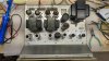
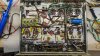
Here are some pictures of the KX-100 after all the restoration and modifications were completed.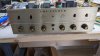
I replaced R71 with Dave’s Zener diode mod and replaced C4 with a 200MF 300V unit which I had on hand. I read (somewhere) that increasing the size of the cathode capacitor would reduce the cathode voltage variation a bit, providing a more stable bias voltage. Not sure if this is true but figured it wouldn’t hurt. The 10-ohm cathode resistors and the 100 Ohm screen stability resistors were also installed.
The bias network was also modified to allow each 7868 output tube to be biased individually. I set each 7868 to 42MA which provided 48V for the heaters of the 12AX7’s.
I then attached my IPAD to the aux input as before and listened to the amp for a while. It sounded quite good to me and I waited for the parts to arrive for the NFB upgrades. In the meantime, I did a side-by side comparison with a similarly restored KX-100 with original Fisher transformers. The amp with the original transformers sounded different for sure, with more “presence”, it was easier to discern the individual instruments and the vocals were clearer, at least to me.
When the NFB parts arrived, I installed them in one channel only initially to see how different the two channels would sound with and without the modification I used a 2.7k/500pf resistor combination as 500pf was the closest I could find to 450PF. Interestingly, 2.7K/500PF is what the fisher 400 uses in it’s NFB network with 7868’s.
The channel with the NFB mod installed definitely sounded better to my ears so I modified the other channel and listened to the amp for a while. It sounds quite good with the NFB modifications, amazing how two components in each channel can change the amp’s sonic characteristics.
Here are some pictures of the KX-100 after all the restoration and modifications were completed.
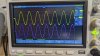
The first trace is a 1Kz sine wave input with the KX-100 volume control set to the 2PM position. The sine wave on both channels is nice and clean. I turned the volume to max briefly to look for clipping and there was none.
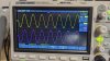
The second trace is a 1Kz square wave with the same volume setting. The square wave is not perfect but is decent to my eyes. Please feel free to comment on my observations!

The second trace is a 1Kz square wave with the same volume setting. The square wave is not perfect but is decent to my eyes. Please feel free to comment on my observations!
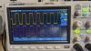
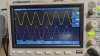

After performing these test traces I checked the 20W speaker loads and found that they were barely warm which seemed odd to me. At the 2 o’clock volume level I would have expected them to be quite warm. I decided to up the signal generator to 500mv output and run another trace at 1Kz. It can be seen in the 7th trace photo. For the photo I turned the volume on the receiver up to max briefly and then back down to 2PM.
The P-P voltage rose to 27V. at max volume and after a few minutes at the 2PM setting the speaker loads were quite hot, too hot to touch for more that a second. This was more of what I expected from an amp rated at 25 WPC.
I am not sure how the Fisher folks came up with 300MV for the AUX inputs. I was using a splitter cable I purchased to derive a left and right input and thought that might be an issue but I checked the output of the cable with the scope and both outputs were correct and matched what was set on the signal generator.
Perhaps the Sylvania 12AX7’s have seen better days…..
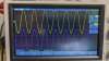
The P-P voltage rose to 27V. at max volume and after a few minutes at the 2PM setting the speaker loads were quite hot, too hot to touch for more that a second. This was more of what I expected from an amp rated at 25 WPC.
I am not sure how the Fisher folks came up with 300MV for the AUX inputs. I was using a splitter cable I purchased to derive a left and right input and thought that might be an issue but I checked the output of the cable with the scope and both outputs were correct and matched what was set on the signal generator.
Perhaps the Sylvania 12AX7’s have seen better days…..
At this point I am going to wrap things up on this KX-100 as I am not sure what further improvement(s) can be made at this point.
Naturally, I am open to suggestions and advice regarding my observations and the conclusions I have come to on this restoration. I am pleased that with the Fender output transformers the KX-100 has been brought back to life!
Footnote: The Fender transformers are now $59.95 each rather that the $42.95 I paid for them two months ago.
Next project is restoring a Fisher 400 I just received!
Enjoy the holidays....
Rich
Naturally, I am open to suggestions and advice regarding my observations and the conclusions I have come to on this restoration. I am pleased that with the Fender output transformers the KX-100 has been brought back to life!
Footnote: The Fender transformers are now $59.95 each rather that the $42.95 I paid for them two months ago.
Next project is restoring a Fisher 400 I just received!
Enjoy the holidays....
Rich
I found a lab exercise online in which the object of the exercise is to plot the Frequency response of an Audio amplifier relative to a reference frequency of 1Kz acting as the Zero DB reference point. I will attach the Lab exercise to this thread as I thought it was quite useful. I plotted the frequency response of both Channel A and Channel B on the KX-100 with the Fender output transformers described in this thread. Calibrating for the 1Kz 0 DB reference point was relatively straightforward. The volume control of the KX-100 ended up at about the one O'clock position. I had to compensate slightly when plotting channel B as the output voltage was a bit higher, I have 2 different grands of outputs in each channel of undetermined quality which may account for the difference.