• The move to the new server is done. There are some software and database maintenance updates in process. This has us passing the hat around to help out. We appreciate any donations. Seriously, even a dollar helps. The payment page may be found here - https://www.audiokarma.org/support.html

Fisher tube chassis balance controls

I need some help!

In evaluating the present condition of the amplifier (minus its original volume and balance control wiring), I am trying to learn just how the controls were wired into the circuitry. So far I have found that the leads from the balance control center lug were attached in this manner: Ch A used a coax that was white with a green stripe to one end of R38; Ch B used a coax that was black with an orange stripe to connect to one end of R39. The grounds of those coax cables are attached to terminal strips near V5 and V6, which makes sense (in the other cables in the amp, usually only one end of the shield is attached to ground to prevent ground loops). So the end of the coax cables at the high side of the volume control was likely not grounded.

What I need to know is: for Ch A, was there a coax cable between C12 and the Ch A volume control high side and if so what were its colors and how/where was it grounded; for Ch B, was there a coax cable between C15 and the high side of the volume control high side and if so what were its colors and how/where was it grounded? How was the low side of the volume control ground handled - how and where was it grounded?

Additionally, which channel connections were to the front elements of the volume and balance controls, Ch A or Ch B? Were the connections between the volume and balance control just point to point wires, or were shielded coax cables used? If shielded cables were used, where was the shield ground of those cables grounded?

Not content to just remove the volume and balance controls, the person who modified the amplifier also cut the 10K ohm resistors away at the grid pins 7 on V5 and V6, showing once again that they had little understanding of the circuits they were messing with. Cutting the coax cables alone would have done the job. Cutting the resistors away at the grids and soldering their added coax cables there created an awful blob of solder and may have caused other problems with the audio depending on the impedance of the preamp driving the output stages.

Joe
 
Joe -- You're going to need the patience of Job to bet through this one!

Fisher classically used the rear control of their dual controls for the Channel A element.

So you're saying the previous modification left the input grid with no grid return path?

Dave
 
My Fisher X-101C Kit

Dave;

I am not sure, as the last person who touched it before I received the unit had also done some removal of parts and re-installed some parts that came with the unit.

I have spent the morning hours re-working the wiring in and around V5 and V6. I have been removing the large component wire lead ends that were still attached to the grids and cathodes in that area. Some of the wire leads were quite large and created near shorts between tube socket pins. It is a minor miracle that this unit ever worked after the modifications had been added.

Thanks for that data point on the control wiring. I am going to assume that the wiring between the balance control and the volume control were just point-to-point wires and that the leads back to the chassis underside used coax cable material. By studying the original schematic I have found the original coax leads that lead back to the grid pin 7 of V5 and V6. The lead to V5 was white with a green tracer and the one for V6 was black with an orange tracer. The Ch A coax from C12 of V3 was a blue with black tracer to the volume control high side. The Ch B coax from C15 of V4 was a black with orange tracer going to the high side of the volume control. Those coax cables had their signal shields grounded at the terminal strips near V3 and V4. Did Fisher ground the end of those coax cables at the volume control or was it left un-grounded on that end?

Was the ground for the volume and balance control done right at the chassis front panel somehow, or were the grounds tied together and the coax leading back to the grid 7 of V5 and V6 grounding the circuit at the ground connection of the coax at the terminal strip near the two tubes?

Or did the shield ground of the coax coming from the output coupling cap feeding the volume control also supply the ground for the volume and balance controls?

So much was removed when the volume and balance controls were removed that it is difficult to determine just how the wiring practice was implemented there. I do know that the center lug of the Ch A balance control used a white with green tracer coax going to pin 7 of V5 through R38, while the Ch B balance control used a black with orange tracer going to pin 7 of V6 through R39.

I hope that these questions have made sense. Sometimes the way I word things might lead to confusion.

Joe
 
The actual grounding scheme that Fisher used typically varies from unit to unit, based on the layout and grounding issues a particular model presents. The best thing would be for a helpful AKer who has one of these units to post some good detail pics for you in the area of interest.

Dave
 
Volume & Balance Control Wiring Issues

Dave;

Perhaps I should make a separate post just related to this subject in case not many people are looking at this thread. I did look at a X-101 schematic and some illustrations and it appears that it is also quite similar except for not having the input selector as pushbuttons. There might be other models quite similar as you said.

Thanks.

Joe

Joe
 
Next Steps

I finished modifying the screen grid circuits of the output tubes by moving the B+ feed to unused pin 1 and then connecting the B+ to pins 4 & 8 of each socket with a 100 ohm 1/4 watt carbon film resistor as detailed in Daves modifications. I then removed all of the cathode bias yellow wiring that was part of the DC supply for V1-V4. Then I installed 10 ohm 1/4 watt carbon film resistors at each tube socket from pin 5 to a ground lance on the tube socket saddle nearby. Each 7591 will now have its own cathode resistor.

I need to get my remaining parts ordered - capacitors needed and the semiconductors. This will take some time carefully checking the dimensions of the capacitors to go on the LV power supply to be sure the completed assembly will fit in the space allowed..

I found some nice small OD audio cables that have colored jackets that I can use in wiring the volume and balance controls to help keep the channels identifiable when servicing. This is one time being a pack rat came in handy.

While waiting for parts I may spend more time cleaning and polishing the sides and bottom cover of the chassis to get it looking better and smelling cleaner.

Joe

Joe
 
Chassis Press-in Nuts

I discovered recently that one of the press nuts on the bottom chassis cover is missing. They have 8-32 size threads. Does anyone have a ready source for these?

These are the nuts that allow screws to hold feet on the bottom or hold the chassis to a wooden cabinet.

Joe
 
I discovered recently that one of the press nuts on the bottom chassis cover is missing. They have 8-32 size threads. Does anyone have a ready source for these?

These are the nuts that allow screws to hold feet on the bottom or hold the chassis to a wooden cabinet.

Joe

I had one of those nuts missing on the bottom cover of an X-100-B. They're easily found at most hardware stores - got mine at Home Depot. I soldered it in with a high wattage iron and it held really well. Good luck with yours.
 
Press-in Nuts

Bruce;

I was at Ace Hardware yesterday and did find some other hardware items I needed. I did not spot any press-in nuts at the time, but the man who normally handles questions about the hardware was not there. I went too early in the day I suppose. I might try again, although a search on their website did not indicate they had any. sometimes just knowing how to describe an item makes a difference between success or failure. Not all websites are as good as others when searching.

I did find the right size of hex-head screws. Fisher used 1/4 hex head screws of No. 6 type as those fit well on the chassis. I was not sure of what size they were, so I bought both No. 4 and No. 6 sheet metal screw threaded types in a large enough quantity to fit all of the spots on the chassis where they were used.

I will likely be at the store again soon and will go later in the day when I can talk to the right person.

Was your soldering iron a 1200W unit?

Joe
 
I don't think you need anywhere near that big of an iron. I have a 225 watt iron with a large solid copper tip that I use to unsolder old and solder in new can caps at the chassis ground terminals. It has no problems doing the job.

Dave
 
Soldering Press-in Nuts

Dave;

Thanks for that input. I have been using my Weller soldering gun for installing or removing can electrolytics for years, but its highest wattage is only 180W, so sometimes it is inadequate. I may look for one similar to what you described.

I called Grayhill this morning to talk to one of their technical advisers about their 44D30-02-4-AJS rotary switch which is in stock at Mouser Electronics. They verified that it is a 4 pole 2 or 3 position switch (selectable) of the make before break type. This particular one is also a double deck switch which is more than I need, but the only one I can get my hands on at present to replace the Mode switch. I am ordering capacitors and semiconductors from Mouser this morning.

I have been tracing out the speaker wiring this morning. I had to repair some more cut wires at the terminal strip near the output transformers where the original common leads of the transformers were connected to the leads going back to the line stages for negative feedback. I reconnected those wires at the terminal strip.

There are still three wires near the back of the chassis that are fabric covered wires going to/from the speaker switch up front. At least one of these wires was originally attached to one lead of the center channel speaker output terminal strip. Looking at some pictures of Don's amplifier it appears that there was an orange plastic insulated wire from one center channel speaker terminal that connects back to one of the other speaker terminals, but I cannot see exactly which one. I have not yet determined where the other two fabric covered wires were attached, but should soon find the answer.

It will be a busy day.

Joe
 
Parts Ordered

Today I spent time going over the details of the capacitors needed for the modifications. I put together a list at Mouser and have those plus some of the semiconductors on order from them.

The one semiconductor I could not find was the KSA10130BU transistor which Dave says is the same as a 2SA1013 transistor. I found 10 on ebay at a decent price with free shipping. Otherwise the on-line companies required a $20 or more minimum order.

I am going to try one more time at Ace Hardware for the press-in-nut for the chassis bottom cover.

Joe
 
Original Speaker Wiring Sanity Check

Dealing with the cut wires in this unit is no picnic! I am seeing 3 fabric covered wires that come to the speaker terminal strips at the rear of the chassis. I think I have figured out where they go, but I need someone to look at their X-101C and verify.
1) a White fabric covered wire goes to the common lug of the Ch B speaker terminals.
2) an Orange fabric covered wire goes to the common lug of the Ch A speaker terminals.
3) a Red fabric covered wire goes to the X lug of the Center Ch. speaker terminal strip.
4) an Orange plastic covered wire connects from the Center Ch. speaker Y lug to the Ch B 16 ohm speaker terminal strip

The fabric covered wires mentioned above come from the speaker/earphone selector switch at the front of the chassis. That switch also has another White fabric covered wire that connects to a 2-lug terminal strip near where the output transformer wires come through the chassis. Looking from the back of the chassis the white wire connects to the left lug. A Brown fabric covered wire comes from the speaker switch to the right lug of that same terminal strip. There are plastic insulated wires that provide the negative feedback to the line/driver stages that connect with the White and Brown wires at that 2-lug terminal strip. The Output transformer Black Common leads connect to those two lugs of the terminal strip, one for Ch A and one for Ch B.

Do I have the original speaker wiring correct?

Joe
 
Last edited:
Joe -- I've got to give a shout out to Mouser. No minimum order, fast and reasonable shipping. For known first run semiconductors, it's pretty hard to beat their prices.

Regarding the soldering gun, I have found that while yes, it does take wattage, the real key is tip mass. The 225 watt iron I use has a solid copper tip whose exposed area is 1/2 inch in diameter, and 2 inches long. This acts like a reservoir as surly as a large power supply cap does to an amplifier circuit. It only needs to touch the chassis for a few moments, and surely gets the job done well. I suppose that for assembly line work, where repeated chassis soldering connections are being made, then more wattage would be required. But for my lab needs, where such connections only amount to one or two at best at a time, it's been a stellar performer.

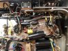
I've included an in-progress pic of a Fisher 400C preamp I'm currently finishing up. In it you will see two T-strips I added to properly execute some of the work/modifications involved. One is at 9:00 on the on the pic face, and the other is at about 4:30, both near the edges of the pic. I mounted them by soldering them directly to the chassis. You can see that the solder for these mounting connections flowed very evenly and smoothly, indicating adequate iron temp, and lacking the oh so typical ragged look that using even a high wattage gun produces. The strips are very firmly anchored to the chassis this way, without actually altering it by drilling.

I hope this helps!

Dave
 

Attachments

  • SAM_1391.jpg
    SAM_1391.jpg
    121.4 KB · Views: 31
Modified Negative Feedback and Speaker Wiring

Dave;

After some detective work on the wiring in this X-101C, I think I see that the modifications involve adding two wires from each channel to the associated line/driver stage. A new 16 ohm feedback wire and a 4 ohm feedback wire. While the original 4 ohm connections tied negative feedback wires at the 2-lug terminal strip where the White and Brown wires come from the speaker/earphone switch the new wires can go direct from the output speaker terminals to the line/driver stages. In fact it may be best to disconnect or even remove the original feedback wires from those two terminal lugs near the output transformers and ground the two transformer black common leads there at the ground lance.

I assume that the added .0024uF, 1200 ohm resistor and 620pF capacitor are added near V5 and V6 on terminal strips.

Joe
 
They are. I don't know if I have any hi res photos of the modified phase inverter area or not , but I'll check.

Dave
 
Bruce;

I was at Ace Hardware yesterday and did find some other hardware items I needed. I did not spot any press-in nuts at the time, but the man who normally handles questions about the hardware was not there. I went too early in the day I suppose. I might try again, although a search on their website did not indicate they had any. sometimes just knowing how to describe an item makes a difference between success or failure. Not all websites are as good as others when searching.

I did find the right size of hex-head screws. Fisher used 1/4 hex head screws of No. 6 type as those fit well on the chassis. I was not sure of what size they were, so I bought both No. 4 and No. 6 sheet metal screw threaded types in a large enough quantity to fit all of the spots on the chassis where they were used.

I will likely be at the store again soon and will go later in the day when I can talk to the right person.

Was your soldering iron a 1200W unit?

Joe


Joe, forgive me for I used just a regular 8-32 nut not a press-in. My iron was a 150w stain-glass iron. And, as Dave says it has a large tip mass and very effective in soldering things to chassis. I use it attach terminals, electrolytic can tabs, etc.

You're doing an amazing job with your X-101C!
 
Speaker & Feedback Wiring + Press-in-nuts

Dave, Tube-a-Lou & Bruce;

Thanks for your comments, compliments and information. It all does help. I think I will use a yellow wire for the 4 ohm feedback and a blue wire for the 16 ohm feedback. Too bad I don't have a brown wire with blue stripe!

Looks like the order coming from Mouser will arrive Saturday. It will probably get here while I am at the Vintage Antique Radio & Phonograph Society swap meet in Irving, TX. The swap meet runs from 8AM to Noon. The president of the group, Jim Sargent, has a large collection of knobs and has some of the small Fisher knobs with fluted edges and the brass trim cap which were used on many receiver tuning and volume controls. I need two, one for the volume and one for the mode switch.

Bruce;
If I can't find an 8-32 press-in-nut of the right type, I may just do what you did. Of course I will need to get a high wattage iron such as the one that you and Dave use. I have from time to time needed a higher wattage iron. This will be an excuse to get one. There is nothing like having the right tool for the job.

The green jewel is missing on the front panel, so I will need to get one of those. Did the dial lamp that shines on the jewel have a shroud around it to keep light from shining into other areas not desired?

Joe
 
Back
Top Bottom