• The move to the new server is done. There are some software and database maintenance updates in process. This has us passing the hat around to help out. We appreciate any donations. Seriously, even a dollar helps. The payment page may be found here - https://www.audiokarma.org/support.html

Fisher x-101-st Project Amp

On your good advice, I have decided to restore this amp instead of my previous misguided idea of making a power amp out of the pieces. I'm reversing course before I make a bigger mess of things, but have already learned a lot about why the "simple" path I started with was not simple, and was (almost entirely) wrong. I am very close at this point to undoing everything I have done so far (unhooking the tape outputs was the biggest problem because I ungrounded a bunch of stuff, along with V1 and V6 removal fiasco that blew the 100mfd capacitor, which has now been replaced - V1 and V6 still glow quite a bit brighter than the other 12ax7s, but not like lightbulbs, as they were before).

The amp is now working again (kinda) in channel B, but channel A is dead. When I use the mono switch to troubleshoot this issue, I get the following results:

stereo reverse: strong channel B in the left speaker (tone controls?)
stereo: weak channel B in the right speaker
channel A: both speakers silent
channel B: both speakers play, strong left weak right

I am almost positive that there is something wrong with the way I've hooked up the balance pot, but I can't figure out what I've done wrong. It is behaving very strangely: when the mono switch is in the normal stereo position and I turn the balance pot to the right (increase channel B) the right speaker gets quieter (left is silent). When I switch to stereo reverse however, then turn the balance pot to the right (increase channel B) the left speaker gets louder (right is silent).

Another possible clue: when I have the mono switch in the normal stereo position, the bass and treble controls do not work. When reversed, the tone controls work. When I put both tone controls flat, and switch back and forth between stereo and stereo reverse, the channel B in the left speaker (reverse) sounds better musically than in normal stereo, but I can get them to roughly match in both volume and tone by turning down both bass and treble by about 4 db. This makes the reversed channel B in the left speaker sound equally as horrible as the right speaker in the normal stereo position. As you might expect given this description of behavior, when I have the mono switch set to channel B in both speakers, the tone controls only work on the left speaker.

At this point (and I am pretty sure this is how it was hooked up when I got it and both channels worked), there are two shielded wires connected to the pot, and one unshielded. The unshielded (black) wire is connected to the center pin and runs somewhere into the preamp rat's nest, but I think this is ground, and I have never removed the other end of this wire. The shields of both shielded wires are also connected to the center pin. The center conductor of each shielded wire is connected to one or the other outer pin.

What confuses me is that the shield is completely unconnected on the other end, literally cut and taped off, while the center conductors are each connected to pin 7 of the 12ax7 voltage amps (V3 and V8) via 68K resistors (R64 and R66). Obviously I am missing understanding of a very basic topic here.

Can anyone assist me getting this balance knob working properly again?
 
Some good close up pics will be the quickest way to resolve. The volume control appears to have been replaced on this unit, so there could be issues with its wiring as well.

Dave
 
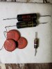
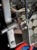
Back to work on this amp, I have some coupling capacitors, RG-174, and resistors on the way, and feel like I have things wired very close to the way I originally received it. I intend to install a safety capacitor also. Next step will be replacing the volume knob/switch, and rewiring the loudness circuit. Here are some photos of current condition - burnt, then hacked. Thanks to everybody who advised me to restore rather than continue hacking. I am really looking forward to using this amp as original.

20200216_153835.jpg 20200216_153850.jpg 20200219_095131.jpg 20200219_095920.jpg
 
I am getting much closer after replacing a few parts. At this point, I have replaced the following:
* 100 uf electrolytic that blew after removing V1 and V6
* .01 uf cap at mains (replaced with X1/Y2 safety cap)
* .047 uf coupling caps replaced
* 4.7 k resistor in power supply (it was reading 5.3k)
* balance knob wiring
* 12ax7 voltage amp/phase inverter tubes

I am using the Executive V console schematic, as it is the most accurate schematic for my unit of the three posted elsewhere in this thread.

At this point I feel the circuit is fairly safe for me, though I have taken no operating measurements so I am not sure of the safety of the parts, or whether everything is perfectly in spec. I measured all of the resistors in circuit and only had to replace one. I don't feel like it is going to blow up or smoke if I leave it playing for a bit. There was a small blue spark by the rectifier tube right after I turned it on the first time after recapping, but I haven't seen it since, and it appears to be working normally since.

I have not replaced the power supply filter caps yet, though I am sure it has been recapped in the past, as I found clipped, abandoned leads on all of the coupling cap terminals and tube sockets (I desoldered everything and removed them before installing the new caps). So the filter caps may be newer, though I don't know how to test them for leakage with the equipment I have, and am not sure of the downstream effect of leaky caps in the power supply.

So at this point I think I am really troubleshooting a left channel miswiring problem, as I have swapped the voltage amp/tone control tubes several times to the same results. I found one 12ax7 with hum and have sidelined it, and two others that started motorboating after warmup, so I have those in position as V1 and V6 preamp tubes. Since I am not using that section for audio, the heaters seem to work fine as bias resistors. I'll replace them when I get to the point of hooking up my turntable.

The previous confusion with the balance knob/stereo switch is gone after the rewiring with fresh rg-174, and it works as expected with a bad channel A. It sounds like perfect mono when I use the channel B setting, and the balance knob works. Apparently I had that miswired before.

Because the amp section seems to work normally when fed channel B, I am going to focus on the preamp section for troubleshooting. I have swapped output tubes and things sound identical.

I guess it could be the volume knob - I haven't confronted that mess yet (the original mess before I got it), though I have acquired a proper switch from notdigital to replace the burned out part. The volume knob is an obvious replacement unit (not D shaft), and I don't fully understand how to restore the loudness circuit, so any advice on this is appreciated.

My other guess is that the channel A record out/monitor jacks are still miswired, and I am going to go over all these connections in detail today.

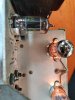
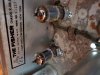
20200306_201727.jpg 20200306_201759.jpg 20200306_201814.jpg 20200306_202349.jpg 20200306_202507.jpg 20200307_115517.jpg 20200307_121138.jpg 20200307_144245.jpg 20200307_144317.jpg
 
Second from last pic- those 'ax7's are doomed if they're subjected to such excessive filament voltage for very long. Find out the cause & fix that. They won't be cheap to replace, as it seems like everybody wants 'em & are willing to pay stupid money for them. Definitely get the power off the front panel switch. Even with paralleled contacts as wired, that switch shouldn't be handling the power surge. It likely won't for long. The original switches on the volume pot are notoriously fail-prone on most Fisher tube gear. Replacements are , in my opinion, not worth the time, $$$, & hassle to replace. I've just bypassed at the switch on one of my Fisher tube units, use a power strip for power control or, I'll use my DBT/variac ( with the dbt part bypassed) . Just twist it from 0V to line voltage. Easy on the stock caps & everything like that.
 
Thank you very much for the direction, I think I have found the excessive voltage problem, and it will likely fix the channel A problem also. I have some desoldering and resoldering to do.
 
Ah, stereo! Those Fisher engineers really knew what they were doing with this new technology.

After undoing the last of my hackery from earlier in the thread, things are better than they have ever sounded, the filaments in V1 and V6 look normal, and all the controls work as expected. I don't even know how that miswiring happened - if I had been following a schematic or even thinking about it just a little bit I never could have soldered the connection. Ultimately, I determined I had erroneously jumpered the ground wire to the center pin of the monitor jack, and connected the center pin of the tape out jack directly to ground. I figured this out from tracing the schematic backwards from the V1 and V6 filaments, thank you Catmanboo for the guidance.

Now on to the switch, volume knob, and loudness circuit, the previous hackery. I have already acquired a switch with the guidance to install a thermistor to handle the surge, so would like to take this all the way.

The current volume pot is not a d-shaft, so not original. I'd like to replace it but cannot really find a perfect replacement. What is the best way to approach that?

Also, is there any good way to clean the rust off the chassis?
 
Finding a stock volume pot in good working order will cost you some $$$$. Even the replacement pot available at auction is pricey. I wouldn't do it. IF the pot you now have is operational, I'd kiss the loudness circuit goodbye, attach the switch, and be content. Personally, I hate not being able to restore to stock; but compromises sometimes have to be made.

Re: rust. If there is rust, then it has eaten through the plating onto the steel bed. Nuttin you can do about it. except remove the rust with wet/dry sandpaper (or some extremely fine sandpaper,) and wax it over. On a couple of occasions where feasible, I've put on a light spray of silver spray paint to cover the ugly. Sometimes, I've sprayed into a container, and touched up spots, mostly to keep the rust at bay. Everything I own is in a cabinet so it's easy to say "out of sight, out of mind."
 
Evaporust on a towel left to soak will get rid of the rust but leaves dark spots in place of it. Even if you paint over it using that first will keep rust from growing back under the paint
 
Evaporust on a towel left to soak will get rid of the rust but leaves dark spots in place of it. Even if you paint over it using that first will keep rust from growing back under the paint
Gadget, is that aka phosphoric acid? Multiple brand names for essentially the same thing, I think. (Ospho, for one)
 
I am looking for some guidance on next steps for this amplifier, as it is sounding pretty good, but I can clearly see crossover distortion in both channels near clipping, and can hear some hiss and hum when I turn up the volume all the way with no signal. It is better since replacing the can capacitors (Hayseed Hamfest), but I am not sure what to expect with this amplifier. How quiet can I get it?

So far I have replaced the can caps, power switch (adding CL-80 thermistor), 0.047 uf coupling caps in the amplifier section, and the 4700 ohm resistor in the power supply. The loudness switch is unfortunately permanently disconnected as it needs a volume pot with loudness taps. I have acquired all the caps for the preamp section, and many of the resistors for both the preamp and phase inverter sections, but want to replace things part-by-part to isolate the hiss/hum/crossover distortion.

What is the best way to start if I want to get rid of the crossover distortion first? I understand it to be a product of the push-pull design, so it seems like it must be an issue between the phase inverter and outputs, but I have one old Sylvania 12ax7 that acts like a "magic tube" in the tone/input amp position, almost eliminating the crossover distortion for the channel it is installed in. I am getting 32v p-p into 8 ohms and 24v p-p into 4 ohms with this tube - I have other old Sylvanias, new Tung-sols, and new TADs, and while some of them can reach this output level without clipping, they all have strong, visible shoulders in the waveform at the crossover point. The fact that this tube in this position can alter the crossover distortion makes me think twice about my assumption that crossover distortion must be between the phase inverter and output sections.

I have measured the voltages as follows:
GZ34 405v (415-430v according to Fisher and SAMS schematics)
60uf 389v (405v supply)
40uf 331v (350v supply)
20uf 293v (305v supply)
40uf 248v (260v supply)
40uf 195v (185v supply)

All of the output tubes are getting 385v on the plates, 330v on the screens, 20v on the cathode, and 7.5v on the grids - should be 400-350-21-8.5 (400-350-24-12 according to SAMS)

At this point I am thinking it could be low voltages on the amp/phase inverters, as they are low across the board:
af amp - 94-96v plate (jumpered to phase inverter grid), 0v grid, .66-.75v cathode - should be 105-0-1.1 (105-0-.7 according to SAMS)
phase invertors - plate161-166v, grid 94-96v, cathode 94-96v - should be 210-105-105 (220-105-110 according to SAMS)

The voltages on both of the tone/input amps are pretty good, 150-160v on the plates, 0v on the grids, and 1v on the cathodes.

So I have my eye on the plate resistors for the phase inverters - does this seem like the best place to start looking for the crossover distortion? Is there something else I should measure to give me a better idea of where to start?

20200324_213112.jpg 20200324_213050.jpg
 
Gadget, is that aka phosphoric acid? Multiple brand names for essentially the same thing, I think. (Ospho, for one)

No, but the end result looks about the same. I don't honestly know what the magic ingredient is, but its not acidic. SDS says water, "proprietary non-haz chelating agent" and "proprietary non-haz detergent". Doesn't smell like an acid, kinda just smells like hand soap.

GZ34 405v (415-430v according to Fisher and SAMS schematics)

the fact that all your voltages are on the low side makes me suspect the rectifier is a bit weak. Whats the input voltage? If that is reduced for some reason, all of this will be low too. This is cathode biased, and getting over-biased near peak output is something they tend to do. This might just be par for the course if nothing changes with a bit more B+. Its not that far off spec.

Something you might try is Dave's diode fix across the phono tube heaters. It will keep the cathode voltage from swinging as far positive and messing with the bias. Its also good for the phono tube heaters.

https://audiokarma.org/forums/index...ers-heater-string-cathode-bias-system.904119/
 
Last edited:
the fact that all your voltages are on the low side makes me suspect the rectifier is a bit weak. Whats the input voltage? If that is reduced for some reason, all of this will be low too. This is cathode biased, and getting over-biased near peak output is something they tend to do. This might just be par for the course if nothing changes with a bit more B+. Its not that far off spec.

Something you might try is Dave's diode fix across the phono tube heaters. It will keep the cathode voltage from swinging as far positive and messing with the bias. Its also good for the phono tube heaters.

https://audiokarma.org/forums/index...ers-heater-string-cathode-bias-system.904119/

I was also taking a look at that. The straight B+ coming off the rectifier is 405v, while Fisher specs it at 430v and SAMS at 415v. However, I have two GZ34s - an old Mullard, and a new Tung-sol, and both measure pretty much the same, with the Tung-sol only 1-3v higher at every point. I was getting 415-418v off the rectifier before installing the CL-80 thermistor. Now that I review my notes, it does seem to have reduced plate and screen voltage by 10-12v in the output section, as well as 20-30v lower for the phase inverter plates.

I installed the thermistor on the hot side of the mains right before the switch. Is this the right place to install it?

I have checked the large resistors in the power supply and they are very close, starting with a pair of 250 ohm in parallel (115 ohm in some of the schematics) for the 405v supply, 2200 ohm for the 350v supply, then the 4700 ohm that I replaced for the 305v supply. Is it possible that these are misbehaving at higher temperatures when in service?

I am going to take a look at the diode fix for the phono tube heaters. According to the schematics, V1 and V6 filaments are involved with the output grid bias, which is also low (7.5v while Fisher specs at 8.5v and SAMS at 12v). I have seen a couple of videos where crossover distortion was eliminated by increasing grid bias, so that seems like a better direction than messing with plate resistors. The crossover distortion only appears when I increase the output beyond 75% or so, as you described.
 
Very late reply but....

You picked the right place for your thermistor. Hot side is best, but I've put them on both sides.

In terms of voltages, as long as they are within 15% of the schematics they are typically good. Since they are low though (rather than high which is more typical) then you may want to check the rectifier is strong enough to supply everything the amp is requesting under load. That might be related of your problems with the PI's having cross-over distortion problems - maybe you are experiencing voltage sag and that might be messing with the cross-over points for the PI's.

I responded because I just picked one up from the big auction site. It is in rough condition, but that is my MO. I like these basket cases and I like to save them. Good luck with yours. It is a bit of stereo history and they are somewhat rare. I'll be interested to hear if you resolve your final issues.
 
I am a bit stalled out on mine as it sounds so good, even though I can easily see crossover distortion in the waveform at higher power levels. I suppose I don't listen at that volume, so can't ever hear it, but would still like to tune mine up further, so post again if you have any epiphanies while working on it.
 
Back
Top Bottom