• The move to the new server is done. There are some software and database maintenance updates in process. This has us passing the hat around to help out. We appreciate any donations. Seriously, even a dollar helps. The payment page may be found here - https://www.audiokarma.org/support.html

Fisher X-202-B - Left channel cuts out at low volume.

Nope those are originals. As is that big sucker just to the left of them.
Cool! Well, thanks for schooling me. I need it :).

Now to go about cleaning them, any suggestions?

Also, I'm going to try to rig up a… rig that will let me turn it upside down while hooked up to speakers so I can try to replicate the issue with a chopstick per Dave's recommendation.
 
Turn it upside down and hold on to the back end. lower it gently to the table or bench and check for what touches 1st. If the transformers touch 1st, you're OK. If the tubes touch 1st, you'll need some blocks under the transformers to raise it up a little. I turn my gear over all the time, as long as the transformers touch 1st. Blocks make that happen. You don't need anything special.
 
Turn it upside down and hold on to the back end. lower it gently to the table or bench and check for what touches 1st. If the transformers touch 1st, you're OK. If the tubes touch 1st, you'll need some blocks under the transformers to raise it up a little. I turn my gear over all the time, as long as the transformers touch 1st. Blocks make that happen. You don't need anything special.
Awesome idea. Okay. Tomorrow is the day I figure this out once and for all… hopefully without killing myself! :)
 
Turn it upside down and hold on to the back end. lower it gently to the table or bench and check for what touches 1st. If the transformers touch 1st, you're OK. If the tubes touch 1st, you'll need some blocks under the transformers to raise it up a little. I turn my gear over all the time, as long as the transformers touch 1st. Blocks make that happen. You don't need anything special.
Alrighty! larryderouin and dcgillespie, you were 100% correctomundo!

I flipped it upside down again, took a closer look at the V6 coupling caps (which definitely do not look new to me anymore) and saw that one of those caps has some crust around one of the poles. Using a popsicle stick I was able to move it around a little and recreate the issue. Now I know what the issue is thanks to the two of you!

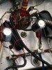
Now on to cleaning it… do I just deoxit the poles & solder joints with a q-tip or do the coupling caps need to be replaced? What's the best way to eliminate the problem? Below is a pic where one end of the cap seems to be a bit of corrosion — though Dave had said that these don't typically leak like other caps would so I'm not sure that it's unusual to see that.

The circle at the top is where I used the stick to recreate the breakup. It seems to be coming into contact with the lead above it. Should I try to carefully bend the lead away from the cap pole?

The circle at the bottom is where the gunk is. Should that be cleaned off?
 

Attachments

  • IMG_1847.JPG
    IMG_1847.JPG
    68.3 KB · Views: 41
Last edited:
Glad you found it! However, unlike components that can be cleaned, mylar caps cannot. They are a sealed component, so that the cleaning fluid cannot enter the cap. Therefore, it needs to be replaced. When caps like this "leak" we are referring to them leaking electrically. That is, they are allowing DC voltage to pass through them, whereas a good cap will not allow any DC voltage at all to pass through it. A good cap only pass AC voltages.

The other thing they can do is become intermittent where the leads connect inside the cap -- which is apparently what has happened in this case. When the connection becomes intermittent, it can cause all manner of problems with the signal passing through the cap.

That cap is a .047 uF, and should be replaced with one rated for 600 vdc.

Dave

 
Glad you found it! However, unlike components that can be cleaned, mylar caps cannot. They are a sealed component, so that the cleaning fluid cannot enter the cap. Therefore, it needs to be replaced. When caps like this "leak" we are referring to them leaking electrically. That is, they are allowing DC voltage to pass through them, whereas a good cap will not allow any DC voltage at all to pass through it. A good cap only pass AC voltages.

The other thing they can do is become intermittent where the leads connect inside the cap -- which is apparently what has happened in this case. When the connection becomes intermittent, it can cause all manner of problems with the signal passing through the cap.

That cap is a .047 uF, and should be replaced with one rated for 600 vdc.

Dave
Yeah after re-reading your original reply about the coupling caps I figured it was probably going to need to be replaced.

I'll reach out to AEA to see what they can do. My soldering skills are okay at best but I certainly do not want to damage anything.

Should both caps be replaced or just the faulty one? I would assume that they both should to keep the channels balanced. Or does it not matter? Finally, would it be best to have all of the coupling caps replaced or is it only necessary to replace the ones on V6 for now?
 
Last edited:
While the bad connection might be inside the cap, it's also possible that there is a bad solder joint at one or both ends of the cap. I'd suggest reflowing the solder at both ends before replacing the cap. If you can solder, this is a fairly simple job. If it's not just a bad solder joint and the cap needs to be replaced I'd suggest measuring the other caps for leakage with a meter. If they measure reasonably well, leave them alone. If not, replace.
 
While the bad connection might be inside the cap, it's also possible that there is a bad solder joint at one or both ends of the cap. I'd suggest reflowing the solder at both ends before replacing the cap. If you can solder, this is a fairly simple job. If it's not just a bad solder joint and the cap needs to be replaced I'd suggest measuring the other caps for leakage with a meter. If they measure reasonably well, leave them alone. If not, replace.
Thank you, FlaCharlie! If it needs to be replaced would it be best to replace both coupling caps on V6?

When I had the amp serviced and modified by AEA, they checked all caps for leakage and all solder joints. Obviously that doesn't mean they couldn't go bad afterward as demonstrated with the coupling cap on question. So, I'll be sure check the others.

You all are a fantastic resource. Thank you for taking the time to help a novice.
 
Oh and any recommendations on coupling cap replacements? I've heard great things about Mundorf. Dave had said it needed to be .047uF @ 600vdc
 
Orange Drops (715P) or Illinois Yellow Axial's. You don't need Mundorf's, Solen's or other Boutique caps. They don't improve or change the sound appreciably and they DO EMPTY you wallet a lot faster.
 
Orange Drops (715P) or Illinois Yellow Axial's. You don't need Mundorf's, Solen's or other Boutique caps. They don't improve or change the sound appreciably and they DO EMPTY you wallet a lot faster.
Haha. Yeah, I definitely want to avoid that if it's not going to make a difference in sound quality.

I grabbed a few of the Orange Drops (715P) in .047uF & 600VDC and will replace both of the coupling caps on V6. Going to have a tech look over the others too to make sure they're not leaking current.

Quick question: I know it's important to keep the uF rating the same, but is it important to match the voltage or is it okay to go a little higher since it's the max voltage? Just curious as I saw that the Illinois Yellow Axials come in .047uF but with a 630vdc. Couldn't find them in 600v.

Thanks again!
 
600V or 630V is perfectly fine in this application, and offers a nice safety factor over the original 400V pieces.

Dave
 
I agree with Larry about the caps. I believe those Orange Drops and the Illinois are the same construction as the stock caps. Going to a higher voltage rating is OK, 630v is a fairly standard rating these days. If you can solder, I suggest you do this yourself. If you don't have a meter you can find one fairly cheap and measure for leakage yourself. Your comment earlier about the cost quoted to replace the pot ($160 plus labor!) seemed really high to me. You're in California though so . . . ??? My house would probably be worth 10 times as much if it was in Frisco.
 
I agree with Larry about the caps. I believe those Orange Drops and the Illinois are the same construction as the stock caps. Going to a higher voltage rating is OK, 630v is a fairly standard rating these days. If you can solder, I suggest you do this yourself. If you don't have a meter you can find one fairly cheap and measure for leakage yourself. Your comment earlier about the cost quoted to replace the pot ($160 plus labor!) seemed really high to me. You're in California though so . . . ??? My house would probably be worth 10 times as much if it was in Frisco.
It was $160 including the labor. Definietly seemed high to me regardless. Luckily, the power/volume switch works great!

Ok, so my soldering skills are somewhat decent. I'm definitely okay with putting in the caps myself. However, I don't know how to read a schematic. Since I know where the problem lies, I feel that it shouldn't be too much of An issue.

There doesn't seem to be any markings for +/- on these caps and the leads look to be the same length. Is that correct? If so, it doesn't matter which way I put them in correct?

Finally, I don't have a voltmeter but will pick one up. Like you said, I may as well check the other old caps while I'm in there. I am really enjoying learning this stuff and am very appreciative of the time you all provide. Cheers!
 
Caps smaller than 1.0uf tend to be some sort of FIlm cap, BI-POLAR or NON DIRECTIONAL, although there are sub 1.0uf polar electrolytic caps out there they tend to be larger than .1uf. All of the caps shown so far are fractional uf so they are bipolar and have no directionality. So either way is fine. Some will be Radial (leads on the same side) or axial( leads on the ends). Both are correct but up to you which one's you want to use, depending on how close the leads to be soldered to are.

Jeez last time I checked a 3 bdrm 1 bath 1000sqft ranch in Md that cost $250K is about $1.3M in the Bay Area. I could have made a killing if I had bought some real estate in SFRAN in the late 70's and sold them within the last year or so. But you know how Uncle Sammy likes his cut. The IRS is worse than a Mafia loan shark.
 
I could have made a killing if I had bought some real estate in SFRAN in the late 70's and sold them within the last year or so. But you know how Uncle Sammy likes his cut. The IRS is worse than a Mafia loan shark.

You must have some very reasonable Mafia loan sharks in Md. Larry!

People who are in the 10% and 15% brackets pay no tax on long-term capital gains. You can be in highest ordinary income tax bracket — 39.6% — and still pay no more than 20% in long-term capital gains taxes.

https://www.nerdwallet.com/blog/taxes/capital-gains-tax-rates/
 
Caps smaller than 1.0uf tend to be some sort of FIlm cap, BI-POLAR or NON DIRECTIONAL, although there are sub 1.0uf polar electrolytic caps out there they tend to be larger than .1uf. All of the caps shown so far are fractional uf so they are bipolar and have no directionality. So either way is fine. Some will be Radial (leads on the same side) or axial( leads on the ends). Both are correct but up to you which one's you want to use, depending on how close the leads to be soldered to are.

Jeez last time I checked a 3 bdrm 1 bath 1000sqft ranch in Md that cost $250K is about $1.3M in the Bay Area. I could have made a killing if I had bought some real estate in SFRAN in the late 70's and sold them within the last year or so. But you know how Uncle Sammy likes his cut. The IRS is worse than a Mafia loan shark.
Tell me about it! We bought a 3 bedroom 1.5 bath house on a 1/2 acre of land in Baltimore City for $280k. Sold it after two years, made a tiny bit of money from it and moved to San Francisco for work. Our rent for a 2 bedroom apartment doubled what we were paying in mortgage every month! Makes me sick every month when we throw our rent $ into the void.

As soon as I get my caps and multimeter I'll do my best not to destroy this thing. I'll keep you all posted :)
 
Well, I soldered in the new Orange Drops. Did it as cleanly as possible. There were two connections with these two caps where Ken from AEA had bent the leads and wrapped them around the connection taps so it was virtually impossible (for me anyway) to get them off. So I clipped the caps out of there on those ends and joined the new leads with the little ends of old lead left. There just wasn't enough room in there for my hands and I didn't feel comfortable taking a bunch of things out to get to the cap leads in a way that would allow me to remove them cleanly. So, I did the best I could and the connections are solid enough that I'm confident they won't break.

Using good solder and rosin, the end result is fantastic! I haven't had any intermittent left channel problems! On first power up there was a bit of crackle in the left channel and then the same when powering down. Powering it up again, I can't hear anything wrong. The amp sounds great!

Problem solved for today. Let's hope the other old caps last a few years more :) Cheers to you guys for guiding me and inspiring me to get the job down myself. I couldn't have done this without you.

Best,
Christopher
 
Glad you got it going! And that you did it yourself! It's a great feeling when you can do something like that yourself.

Becoming intermittent is the biggest problem I find with the Fisher coupling caps. It doesn't always happen. But if something is going to happen to one of those caps, in will invariably involve becoming intermittent. If the problem crops up in the future, now you have some idea how to proceed with it yourself before spending any significant money.

Congrats!

Dave
 
Hi again, everyone. I'm reviving this thread as I have just encountered a new issue. A while back I had a tech check everything and he replaced the two left channel power tubes as one 7591 went bad (I believe I mentioned this in another thread). As mentioned earlier in this thread, I always hear a fuzzy sound in the left speaker when powering on the amp and powering it down. Never seemed to do anything else. Maybe some intermittent static here and there.

Long story short, today I heard two violent arcing noises from the left speaker (ADS L710) and then a quiet hum that started to get progressively louder! I quickly shut it off. Like it only started buzzing like that for 3 seconds. I definitely smelled some burning/smoking but didn't see anything. With it powered off and cooling down, I heard some intermittent soft "hissing" as it cooled down. I keep it in the original wooden case and I am wondering if that is causing too much heat for the left channel power tubes and causing them to short out too soon.

That said, in the back of my mind I am worried about transformer damage even though TF protection was one of the mods AEA said they performed. I just don't trust that they actually did that as they are not the most communicative group.

Any thoughts or help you can provide would be greatly appreciated.
 
Back
Top Bottom