• The move to the new server is done. There are some software and database maintenance updates in process. This has us passing the hat around to help out. We appreciate any donations. Seriously, even a dollar helps. The payment page may be found here - https://www.audiokarma.org/support.html

Fixed cueing arm lift for Technics sl1300-1400-1500 mk2 series

At about $80 delivered, I decided to go a different route. First I tried to glue the broken cam back together, but two different glues failed after just a bit of testing. I don’t have epoxy, but may try that in the future.

Then I decided to disable the auto return function and use it as a manual turntable. This will at least prevent the stylus from being dragged across the record on the way back. This needs to be done in two places.

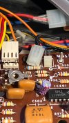
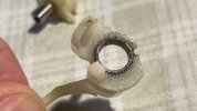
First, disable the mechanism which activates at the end of the record. This is done with the auto return switch at the top right corner of the table. To be sure nobody activates this again, it’s best to disconnect the two pin connector located under the platter and under the large black cover. See first picture.

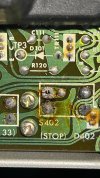
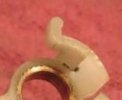
Second, disable the stop button so nobody can accidentally press it and cause the stylus to drag across the record. This is done by flipping the table over, after platter is removed or course, removing the outside edge cover, and the removing some solder. By removing all the solder from one pin, the pin will not touch the board and the stop switch will be disabled. The light on the stop switch will still work, but the switch does nothing when depressed. See picture two. The pin is the second one above the s402 label. See how there is space all around it.

While I did not fix the cueing issue, at least the table can be operated safely now, without fear of damaging the stylus or records.

This table is too good to toss. Manual operation is better than none. Should last another 50 years.

If anyone tries the part from 1200s, please do tell. I’m worried about getting it on the bushing without breaking it.

Thanks
 

Attachments

  • IMG_3636.jpeg
    IMG_3636.jpeg
    188.1 KB · Views: 29
  • IMG_3637.jpeg
    IMG_3637.jpeg
    227.4 KB · Views: 29
  • IMG_3609.jpeg
    IMG_3609.jpeg
    211.9 KB · Views: 29
Last edited:
Having rendered one 1300 MkII inoperable from trying to fix it, I'm leaving my second one as a manual TT with a lifter. It's a great table.
 
At about $80 delivered, I decided to go a different route. First I tried to glue the broken cam back together, but two different glues failed after just a bit of testing. I don’t have epoxy, but may try that in the future.

Then I decided to disable the auto return function and use it as a manual turntable. This will at least prevent the stylus from being dragged across the record on the way back. This needs to be done in two places.

First, disable the mechanism which activates at the end of the record. This is done with the auto return switch at the top right corner of the table. To be sure nobody activates this again, it’s best to disconnect the two pin connector located under the platter and under the large black cover. See first picture.

Second, disable the stop button so nobody can accidentally press it and cause the stylus to drag across the record. This is done by flipping the table over, after platter is removed or course, removing the outside edge cover, and the removing some solder. By removing all the solder from one pin, the pin will not touch the board and the stop switch will be disabled. The light on the stop switch will still work, but the switch does nothing when depressed. See picture two. The pin is the second one above the s402 label. See how there is space all around it.

While I did not fix the cueing issue, at least the table can be operated safely now, without fear of damaging the stylus or records.

This table is too good to toss. Manual operation is better than none. Should last another 50 years.

If anyone tries the part from 1200s, please do tell. I’m worried about getting it on the bushing without breaking it.

Thanks
See my post Fixed cueing arm lift for Technics sl1300-1400-1500 mk2 series. I used a C-c;lamp to press the arm onto the bushing.
 
I just came across this site which has a 3D printer file for the Cue Arm Lever. I have not idea if this will actual work. If someone who has a printer and needs the Cue Arm Level maybe you can try it and let the group know about your experience.

Thanks Dave !

It's great to finally get a .STL file. Now if someone can locate the other style, we'll be set.

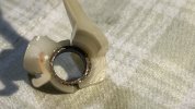
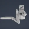
This part looks similar to my broken piece, but mine doesn't have that hump closest to the viewer. Mine is flat along that part of the top and the right side as well. Not sure if that part can simply be cut off, but I doubt it. If anyone has compared both please do tell.

Technics_SL1500MK2_Lifting_Arm.png.webpIMG_3616.jpg
 
Thanks Dave !

It's great to finally get a .STL file. Now if someone can locate the other style, we'll be set.

This part looks similar to my broken piece, but mine doesn't have that hump closest to the viewer. Mine is flat along that part of the top and the right side as well. Not sure if that part can simply be cut off, but I doubt it. If anyone has compared both please do tell.

View attachment 3674030View attachment 3674031
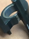
Dan, your part is definitely not the same part. The image for the 3D model I found is basically the same one for either of the two versions found in the SL-1300,1400 and 1500Mk2 turntables. The only difference between the two is the diameter of the hole which holds the bushing. Depending on bushing used determines the ID for the part. You can see the two different types of bushings in the images below; smooth with groove or knurled.
 

Attachments

  • Bushing knurled outer edge.JPG
    Bushing knurled outer edge.JPG
    3.9 KB · Views: 10
  • Arm.jpg
    Arm.jpg
    63.4 KB · Views: 10
Thanks.

So the .STL file on cults3d.com is the flat bushing one. Correct? I wonder if the grooved bushing hole is smaller and maybe can be widened with a drill?

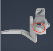
Also, notice the circled area below. My part doesn't have that, but I guess it can be cut off.

Screenshot 2026-01-13 at 9.50.50 PM.png
 
Thanks.

So the .STL file on cults3d.com is the flat bushing one. Correct? I wonder if the grooved bushing hole is smaller and maybe can be widened with a drill?

Also, notice the circled area below. My part doesn't have that, but I guess it can be cut off.

View attachment 3675728
Thanks.

So the .STL file on cults3d.com is the flat bushing one. Correct? I wonder if the grooved bushing hole is smaller and maybe can be widened with a drill?

Also, notice the circled area below. My part doesn't have that, but I guess it can be cut off.

View attachment 3675728
Dan, I don't know exactly what the part this is from cults3d.com but it appears to be the same one I purchased from https://i.materialise.com. There were two different models available one for the bushing with just the groove and other knurled. The only difference between them was the ID of the bushing hole. I don't know how difficult it would be to increase the hole diameter if required but removing the area you have shown in red should be doable.
 
So I had some success with the file available at cults3d.com. The guy who printed this for me was very helpful, and we ended up with three versions of the part.

Part A - was the file with that part I circled in red above removed. My part didn't have that so we removed it. I could not get the knurled brass bushing into the whole without breaking off some of the smaller arms the stick out. This was a failure.

Part B - included the change made in part A, plus he made the hole wider to 9.8mm, and thickened the wall outside the hole by 1mm. While the bushing was a nice tight fit, the extra width made the part too big for the tight fitting parts when installed. So, also a failure.

Part C - included the change made in part A, plus the widening of the hole to 9.8mm. This time everything seemed to fit, but I could still see some differences compared to the broken part I had. After assembling the tonearm, I could feel friction when the tonearm was positioned close to the spindle. I used the solder iron to melt some material in the new part to get clearance of all parts.

I'm not sure how many versions there are of this part. Maybe more than two? My SL-1400 mk2 has the brass knurled bushing and definitely does not have that part I circled above. Maybe that's for a SL-1300 mk2? I haven't tested the muting function yet, but it looks like that arm of the part is correct.

Again, if anyone has these .STL files please do share.

Part aside, I ended up the a super fast dropping tonearm when cueing. The lifting at the end of the record works, but I think it's safer for me to put the needle on the record than lowering it via the cueing arm. I used 300,000 damping oil, but I read that I might need 1,000,000 damping oil. not sure about this.

This was Part B.

Thanks

IMG_3710.jpg
 
Last edited:
So I had some success with the file available at cults3d.com. The guy who printed this for me was very helpful, and we ended up with three versions of the part.

Part A - was the file with that part I circled in red above removed. My part didn't have that so we removed it. I could not get the knurled brass bushing into the whole without breaking off some of the smaller arms the stick out. This was a failure.

Part B - included the change made in part A, plus he made the hole wider to 9.8mm, and thickened the wall outside the hole by 1mm. While the bushing was a nice tight fit, the extra width made the part too big for the tight fitting parts when installed. So, also a failure.

Part C - included the change made in part A, plus the widening of the hole to 9.8mm. This time everything seemed to fit, but I could still see some differences compared to the broken part I had. After assembling the tonearm, I could feel friction when the tonearm was positioned close to the spindle. I used the solder iron to melt some material in the new part to get clearance of all parts.

I'm not sure how many versions there are of this part. Maybe more than two? My SL-1400 mk2 has the brass knurled bushing and definitely does not have that part I circled above. Maybe that's for a SL-1300 mk2? I haven't tested the muting function yet, but it looks like that arm of the part is correct.

Again, if anyone has these .STL files please do share.

Part aside, I ended up the a super fast dropping tonearm when cueing. The lifting at the end of the record works, but I think it's safer for me to put the needle on the record than lowering it via the cueing arm. I used 300,000 damping oil, but I read that I might need 1,000,000 damping oil. not sure about this.

This was Part B.

Thanks

View attachment 3687602

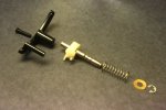
Getting the tonearm to drop at the correct rate was somewhat tricky. I had to take the mechanism apart a couple of times and play with the amount of damping oil; I used 500K. Your are only supposed to put the oil in three groves shown below. I got too much in the first time and it took forever for it to lower onto the record.
 

Attachments

  • Cue Mechanism.JPG
    Cue Mechanism.JPG
    81.9 KB · Views: 11
Back
Top Bottom