• The move to the new server is done. There are some software and database maintenance updates in process. This has us passing the hat around to help out. We appreciate any donations. Seriously, even a dollar helps. The payment page may be found here - https://www.audiokarma.org/support.html

Fixing the Listening Monitor - Yamaha A760II

maxflutehd

New Member
Hi!
So I'm pretty new to the analog audio community and this is kind of my first project.
The Story:
My dad gifted me a broken A760II.
It had some shorted output transistors, which took the drivers and pre-drivers with them. After fiixing up the PSU replacing burnt resistors, some dried up caps (surprised that most were still good ESR) and substituting the shorted transistors it started working again.
It sounds really good!

The Problem(s):
- When I try to adjust the photocurrent check voltage of the PSU, the maxium (the variable resistor maxed out) I can get is 1,05V, the manual specifies 1.2V though. Whats up with that??
- After using it for a while I noticed that the listening level monitor stopped working.

What I already analysed:
- I don't really understand the schematics, yet, and I don't really know how things play together- sadly.
- So, for the photocurrent, I couldn't analyse much.
- For the listening level monitor, I checked the led and the sliding potentiometer.
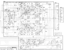
I also checked the IC302 Op-Amp's inputs. The non-inverting input (Pin5) fluctuates down with the music and volume at 0,010-0,200V with the slider all the way right.
The inverting input (Pin6) stays at 1,45V all the time. That gives an output (Pin7) of -16.2V, so the diode blocks the voltage to the LED.

I would appreciate any help and explanation of how the circuit works!!
Thank you so much!
 

Attachments

  • Screenshot 2023-11-25 174651.png
    Screenshot 2023-11-25 174651.png
    155.4 KB · Views: 11
  • Screenshot 2023-11-25 181402.png
    Screenshot 2023-11-25 181402.png
    470.2 KB · Views: 13
Register to hide this ad
When I try to adjust the photocurrent check voltage of the PSU, the maxium (the variable resistor maxed out) I can get is 1,05V, the manual specifies 1.2V though.
Did you use two multimeters for step 3 & 4. These two interact with each other. They are pretty much adjusted simultaneously.. I know it doesn't make that very clear in the procedure for the 760.. But it does make it clear in some of the other X-Power supply models like the M-70 manual.
 
Last edited:
I will try the next days when I find a second multimeter and report back. Do you have any idea about the listening monitor? Would be sad if it didn't work ...
 
One problem at a time.. Got to get the power supply working first. The opto-coupler controls the AC input to the power transformer.
Hey! Thank you, you were right. I always try to fix everything at the same time.
PS issue is solved now. I tested the optocoupler and it was a bit on the weak side. I replaced it with a fresh 4N35 and now I was able (with two multimeters) to dial main voltage and photocurrent check voltage in perfectly. On point 47,5V and 1,200V respectively.
I then continued to follow the guide and dialled the idle currents in. The left one was a bit touchy but I managed to get both at 6,7mV.
May start working as it should once the PS is running correctly.
Im afraid it is not. The voltages I measured in the first post still did not change. Do you know how the voltages should look like on pin 5,6,7 of the IC302 when the monitor is working?
 
Im afraid it is not. The voltages I measured in the first post still did not change. Do you know how the voltages should look like on pin 5,6,7 of the IC302 when the monitor is working?
Have to wait til I get back to my shop. I'm currently at the day job.
 
IC302

No source and no load..

Measured voltages on pins 4 - 8 ( expected voltages in red..)
4. + 16.1
5. + 1.5
6. + 1.5
7. - 15
8. - 16.2
 
Last edited:
I might just get that manual but your help confirmed my suspicion. I got absolutely nothing (0,00v) on pin 5 with no load and no source... The other pins are more or less as expected.
 
What are the expected voltages on 1 and 2 of VR304? Mine are all 0. I bet there should have been a voltage coming in on 1, that's why there is no voltage at pin 5 of IC302, because pin 5 of the IC and 2 of the poti are directly connected to another.
 
I might just get that manual but your help confirmed my suspicion. I got absolutely nothing (0,00v) on pin 5 with no load and no source... The other pins are more or less as expected.
Do you know what this function is for ? Down load the A-960 owners manual. It explains how to use this function.
 
Slide the slider all the way to the left. Then play some tunes with the volume control at say 9 o'clock. See if the LED illuminates.
 
Do you know what this function is for ? Down load the A-960 owners manual. It explains how to use this function.
Yes! I know what it's for. It worked directly after I fixed it, too! But then just stopped working . Where do I find the owners manual for the A960? I can only find the service manual...
Slide the slider all the way to the left. Then play some tunes with the volume control at say 9 o'clock. See if the LED illuminates.
I will try tomorrow, if I play some tunes at this high level they would kill me :naughty:
I bought the manual and the voltages with no load are exactly as in the manual (with exception of pin 7, should be 15.5 but is -15.5, I guess it's an error in the service manual because an op amp would always give out -15.5 under the given conditions)
Tomorrow I will check the circuit coming from the audio output and IC301 as well, I'm thinking there must be a problem somewhere now. It seems that the signal isn't amplified enough...Screenshot_20231128-012140.png
 
Last edited:
You were right. It starts working at about 9 a clock. I never turn it up so loud because I don't want to annoy my flat mates... Crazy. I thought all the way left it needed to work almost from the beginning... So, i need to turn it up so high because I have 4 Ohm speakers connected and the circuit is calibrated for 8 ohm speakers?
Is there a way to modify the circuit for it to start sooner?
Thank you so much for your support till now!!! I appreciate it very much.
I can't download from Hifi engine as I don't have an account yet and they don't accept new memberships :(.
 
Back
Top Bottom