• The move to the new server is done. There are some software and database maintenance updates in process. This has us passing the hat around to help out. We appreciate any donations. Seriously, even a dollar helps. The payment page may be found here - https://www.audiokarma.org/support.html

FM Dipoling For Fun. I Have Some Questions.

Not sure what you mean by time variant.

EDIT: Ooops- duh. Got it now; I was thinking short-term time variation. Yes, the signal strength drops as I move into afternoon. The signal is a bit less quiet but still very useable, but I am not sure why atmospherics might figure in appreciable to FM signals. Might ground conductivity play a role? Not sure why that would be the case either.


OK, here we go.

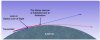
According the the FCC data base the HAAT (height above average terrain) for the radio station antenna is only 66 feet.

Your antenna is what, about 30 feet above ground?

Using these numbers, the direct line of sight path is about 17 miles.

Remember the coverage area map that you posted. The radius of the circle for local coverage is about 20 miles.

The signal can be received farther away because not all of the RF energy is radiated horizontally, the antenna is not perfect and some RF energy may be directed above the "near" horizon. This energy is scattered, refracted, reflected and absorbed on it path to your antenna.

At VHF frequencies the signal may bend a small amount when it reaches it's RF horizon, diffraction at this point, commonly called "knife edging" may help the signal pass the RF horizon. Local conditions in that area may have an affect.

Think Huygens-Fresnel principle in and around the RF horizon.

As the air temperature increases and the sun warms the body of water between you and the radio station the "local" humidity at ground (water) level may may increase.

Line of sight to the radio horizon from the radio station transmitter is about 11 miles. Right about the location of the body of water between you and the radio station.

It will be interesting to see what happens as the season changes and the trees lose their leaves, the air becomes drier and the ground freezes and turns white white.


BTW, the picture is not drawn to scale.
 

Attachments

  • RF SIGNAL LINE OF SIGHT REFRACTION.JPG
    RF SIGNAL LINE OF SIGHT REFRACTION.JPG
    25.1 KB · Views: 14
I had not thought about the Bay. At the low angle of incidence w/respect to the surface, I'd expect primarily reflection, not absorption at the water surface. Do waves in the VHF range exhibit this normal behavior?
 
I had not thought about the Bay. At the low angle of incidence w/respect to the surface, I'd expect primarily reflection, not absorption at the water surface. Do waves in the VHF range exhibit this normal behavior?

I thought you might pick up on some of this.

I gave a you clue, kind of like your science puzzles, when I mentioned the leaves on the trees and that the energy is scattered, refracted, reflected and absorbed on its path to your antenna.

Transpiration, I am sure you know what that is.

For others it is the giving off of water vapor by the leaves of plants.

Transpiration serves to evaporatively cool plants as the escaping water vapor carries away heat energy.

Light, temperature and relative humidity all will affect the rate of transpiration.

The more light, higher the temperature and lower the relative humidity the greater the rate of transpiration.

And Water lost from transpiration can and may accumulate in the boundary layer close to the leaf surface.

So what does plant biology have to do with FM radio reception?

The increased moisture in the air in the "micro-climate" of the tree's canopy can and will have an affect.

Some of the signal passes through the plant material and is attenuated.

So when might one expect the rate of transpiration to be the greatest?

During the time of the highest temperatures, sunlight, and lower humidity.

This might also be the time of the greatest attenuation (reduction) in the field strength of the signal.

That is one mechanism.

With regards to the body of water, remember that the signal from the FM transmitter is a wavefront, is not a beam of energy with a single elevation.

And earth caused refraction, will in simple terms, cause the RF signal to "crawl along the surface of the ground". To keep this simple for this example,it will be a given that there are no structures in the path of the RF signal.

As the signal crawls along in the area of the body of water it will encounter the shoreline. At that point it will encounter an impedance discontinuity. This discontinuity may change with the local micro-environment. There will be some reflection of the direct, incident RF signal, but remember that our RF signal is a wavefront and part of it is crawling along the surface, water and earth.

I mentioned the near radio horizon, but it is not necessarily a single distance, since the RF signal is a wavefront, not a beam.

The will be a weaker wavefront traveling to your antenna. Its field strength may vary due to the above conditions.

This wavefront will pass through various plants while it is still relatively close to the ground and at higher elevations it will pass through the leaves of the trees.

Which brings us back to transpiration and an increase in moisture in the micro-environment of the trees canopy. Again the brings us to variable RF signal path loses as the signal passes though this environment.

Remember that I mentioned that the RF signal is scattered, refracted, reflected and absorbed on it path to your antenna.

Plants, one of the universal disruptors of RF signals. :D

Of course if there are other structures in the path of the RF signal from the radio station, the field intensity prediction becomes that much more complicated.


This is a much simplified explanation.

Since I am not at your location, I offer this information in the most general of terms.

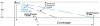
Below is a picture illustrating the vertical beam width of an antenna.

Note that this shows the signal applied to a flat surface, think about in terms of the curvature of the earth and the radio signal horizon and what I have mentioned above. This illustrates how the RF signal does not strike the earth at a single point.

The antenna for your radio station does not have any down tilt, the signal is radiated perpendicular to the antenna. That does not change anything relative to this discussion, other than making the -3dB point farther from the antenna and the point at which it first encounters the radio horizon farther from the radio station antenna.

 

Attachments

  • beamwidth.jpg
    beamwidth.jpg
    14.6 KB · Views: 11
RF choke implementation

Interesting thread with some great technical information - thank you all (especially JBL Guy) for taking the time to write these up and share your knowledge.

I have a related question about installing the RF choke described on page 1. I use a RS FM-6 mounted outdoors, with a 300/75 ohm transformer balun connected at the antenna terminals, then RG-6 Belden coax to my tuner.

My question, would you make the RF choke by simply making the indicated coil in the RG-6 coax near the existing transformer balun or does the RF choke replace the transformer balun?
 
Great thread.AK'rs are some of the best informed most helpful people on the internet.

THANKS!
 
Interesting thread with some great technical information - thank you all (especially JBL Guy) for taking the time to write these up and share your knowledge.

I have a related question about installing the RF choke described on page 1. I use a RS FM-6 mounted outdoors, with a 300/75 ohm transformer balun connected at the antenna terminals, then RG-6 Belden coax to my tuner.

My question, would you make the RF choke by simply making the indicated coil in the RG-6 coax near the existing transformer balun or does the RF choke replace the transformer balun?

In your case the balun transformer takes care of both converting from balanced feed (the antenna) to unbalanced feed (the coax) and matching the 300 Ohm feed point impedance of the antenna to the 75 Ohm transmission line.

A coil would not hurt anything, but probably is not needed in this application.

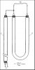
In this case, the RF choke alone will not replace the balun transformer, because in terms of impedance, it is a 1 to 1 ratio device, it does not provide any impedance matching, although one can use a special configuration of coax to provide both the function of a balun and impedance matching.

The picture below illustrates a 4 to 1 (300 Ohm to 75 Ohm) coaxial balun.

For those that like to DIY, they are relatively low loss and work quite well. Of course much more work than a commercial 4 to 1 balun transformer.
 

Attachments

  • BALUN-COAXIAL 4 TO 1.JPG
    BALUN-COAXIAL 4 TO 1.JPG
    26.7 KB · Views: 15
JBL Guy,
Thank you for clarifying the potential redundancy of using a transformer balun and an RF 1:1 choke together. What is the potential insertion loss of your coaxial 4:1 balun?
 
JBL Guy,
Thank you for clarifying the potential redundancy of using a transformer balun and an RF 1:1 choke together. What is the potential insertion loss of your coaxial 4:1 balun?

It would depend on the coax that is used and the quality and accuracy of construction.

On average, lower than a matching transformer, all thought the quality of some of the matching transformers can vary a lot.

Best case, with low loss coax and very careful construction, the loss will be in the ball park of less than 0.2 dB and I have built and measured some for use at 146 MHz (2 meter amateur radio band) that exhibited less than 0.2 dB loss insertion and mismatch loss and one measured about 0.1 dB insertion and mismatch loss.

Average loss at 100 Mhz for a balun transformer is in the range of 0.5 dB to as much as 1.5 dB or more.

How much these small differences in loss may make in reception quality may depend on the particular tuner and local signal quality.

In very weak signal conditions, with the use of a very low noise preamp at the antenna, I like to feed the preamp the most signal possible.

To be clear, in most cases a high quality balun transformer will have sufficiently low enough loss and be much easier to implement.
 
On another note... at home, I am considering a rooftop rotatable Yagi antenna. All of what I see nowadays is advertised as "digital" and my question is, are they tuned to VHF in the same way as the older ones were?
 
TV or FM antenna?

These so called digital TV antennae may by UHF only or combination UHF/VHF high band.

The TV antennae, may or may not provide for FM reception even if they claim FM reception.

I have seen UHF only antennae that the manufacturers claim will have FM reception, of course they also claim 150 mile TV reception.

If a person is looking for FM only reception, a purpose built antenna will provide the best performance and it should cover the FM broadcast band.
 
Last edited:
Yes, what I've seen are described as "HD TV and FM", so not purposed for FM. Those are difficult to find!
 
Yes, for FM reception, the antenna should have an element(s) close to the length of an FM dipole.

The high band VHF TV band covers the frequencies from 174 MHz to 216 MHz.

The low band VHF TV band covers the frequencies from 54 MHz to 88 MHz.

The so called digital TV antennae are either UHF only or combination VHF high band and UHF, with the lowest frequency coverage starting at 216 MHz.

The UHF TV band starts at 470 MHz.

The old antennae would offer some reception of the FM broadcast of the band, but in general, reception of the FM broadcast band was not a priority of TV antenna manufacturers, because of the potential for FM interference to TV channel 6.

This was enough of an issue that it necessitated the use of external FM broadcast band traps in some instances.

As you know, when it comes to RF signal reception, it is location, location, location, so what works OK in one situation, may not work in another.

And with digital TV signals you have a picture or you do not. Gone are the days of a "snowy" picture.
 
Last edited:
OK, here we go.

According the the FCC data base the HAAT (height above average terrain) for the radio station antenna is only 66 feet.

Your antenna is what, about 30 feet above ground?

Using these numbers, the direct line of sight path is about 17 miles.

Remember the coverage area map that you posted. The radius of the circle for local coverage is about 20 miles.

The signal can be received farther away because not all of the RF energy is radiated horizontally, the antenna is not perfect and some RF energy may be directed above the "near" horizon. This energy is scattered, refracted, reflected and absorbed on it path to your antenna.

At VHF frequencies the signal may bend a small amount when it reaches it's RF horizon, diffraction at this point, commonly called "knife edging" may help the signal pass the RF horizon. Local conditions in that area may have an affect.

Think Huygens-Fresnel principle in and around the RF horizon.

As the air temperature increases and the sun warms the body of water between you and the radio station the "local" humidity at ground (water) level may may increase.

Line of sight to the radio horizon from the radio station transmitter is about 11 miles. Right about the location of the body of water between you and the radio station.

It will be interesting to see what happens as the season changes and the trees lose their leaves, the air becomes drier and the ground freezes and turns white white.

Reporting back, post-foliage drop. Signal strength has indeed marginally improved as measured by the LED strength meter. Still no reflective ice or snow, but still waiting.

It is interesting to see that the signal strength very definitely drops when there has been rain. I attribute some of that to the antenna's electrical length changing when wet, as it is exposed. But I wonder how much is due to increased atmospheric moisture
 
Reporting back, post-foliage drop. Signal strength has indeed marginally improved as measured by the LED strength meter. Still no reflective ice or snow, but still waiting.

It is interesting to see that the signal strength very definitely drops when there has been rain. I attribute some of that to the antenna's electrical length changing when wet, as it is exposed. But I wonder how much is due to increased atmospheric moisture

Tyler, thanks for the update. Hope you had a Happy Thanksgiving.

Sorry for the slow response, I deleted the email notification and then forgot to respond. Must be my old age, medications and just barely a double digit IQ on a good day...:D:D:D

Is your coax connection to the antenna well weather proofed?

How is the antenna mounted to the wall?

Are both ends of the dipole in the open?

Of course when the snow sticks to the ground, it will stick to your antenna.

Then you will have a change in performance, but with at least two variables. :D:D
 
Thanks Jbl Guy, very comprehensive trouble shooting. I will do the testing and post back. The florescents seem to take out the weaker signals and by taking out I mean replacing the signal with static.

Were you able to solve your noise problem?
 
Tyler, thanks for the update. Hope you had a Happy Thanksgiving.

Sorry for the slow response, I deleted the email notification and then forgot to respond. Must be my old age, medications and just barely a double digit IQ on a good day...:D:D:D

Is your coax connection to the antenna well weather proofed?

How is the antenna mounted to the wall?

Are both ends of the dipole in the open?

Of course when the snow sticks to the ground, it will stick to your antenna.

Then you will have a change in performance, but with at least two variables. :D:D
Hope you had a restful Thanksgiving!

The dipole is open, connex are weatherproofed with hot glue as sealant. It is not mounted to the wall, rather it is on the roof with one-half of it cantilevered out over the edge. Yeah, I'm aware of the multiple variable problem but this is the solution that worked the best for the locale and building constraints; I did it without permission as it's easier to ask for forgiveness that for permission but the whole thing is pretty innocuous anyway.
 
Back
Top Bottom