• The move to the new server is done. There are some software and database maintenance updates in process. This has us passing the hat around to help out. We appreciate any donations. Seriously, even a dollar helps. The payment page may be found here - https://www.audiokarma.org/support.html

FM - Front End Troubleshooting Tips?

CaseyWKC

Active Member
Hello AKers.

Have a Marantz 2245 where the front end of FM seems to be struggling - but I can't seem to narrow down a particular source.
Stereo FM isn't functional - stereo lamp is good - works in other modes except for AM. The tuner meter doesn't seem to particularly move as I run through the stations, but it does move. Volume is also quite low - but I haven't been able to isolate anything.

Unit has been deep cleaned with deox, power supply recapped, all inputs and AM sound great, issue isolated to FM only. Tuning gang has also been cleaned a couple of times along with the meter tune adjustment tweaked and returned to position to ensure it wasn't just a dirty connection.

I've gone through markthefixer's breakdown of how the FM circuit operates :

IF signal strength is monitored by H306. If IF signal strength is above muting level, H306 is ON, H307 is OFF.
If there is excessive noise, then H552 is ON which is wire-ORed to H307 Collector, keeping H308 (FET) OFF.
If the discriminator is outputting DC due to the tuning being off station, either H560 or H561 is ON which are wire-ORed to H307 as well.

If the station is properly tuned, not noisy and the signal strength is high enough,
H306 is ON, SS OK
H307 is OFF, SS OK AND
H552 is OFF, Noise is OK AND
H560 is OFF Tuning centered AND
H561 is OFF Tuning centered
If SS, Noise and center tuning OK then:
H308 is ON allowing audio signal to pass to the center tap of the 38kHz transformer.
H302, 19kHz amplifier is enabled by H303.
If the 19kHz pilot is present from the broadcast station, then it is doubled to 38kHz by H304 and if of sufficient amplitude to decode stereo, H305 turns on causing the stereo lamp to illuminate.
The left and right matrixed audio signals are recovered by H317-H320, de-emphasis is applied, then they are amplified, filtered of high frequency noise and sent along through the selector switch to the preamp.

I've traced through the IF section, multiplex section, and mute section and all voltages when tuned into a strong local signal - with an FM antennae attached - look perfectly normal.

The only thing that has stood out to me is on H553 - on the P550- muting board - the emitter should be at 0v, I see 1v, the base should be 0, and I see 1.6v.

I've attached a picture of the muting board voltages to see if anybody can provide any insight.

J554 and J559 both lead to the IF board and on the other side of the resistors they're tied to voltages are perfectly normal.

As always, thanks.
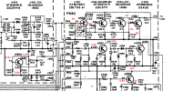
 

Attachments

  • marrantz 2245 p550 muting board voltages.png
    marrantz 2245 p550 muting board voltages.png
    184.9 KB · Views: 25
Register to hide this ad
When you tune across the dial do it slowly. When there is no antenna signal center tune meter should be in the center and signal strength at full left. With antenna connected, tuning to a strong station, muting off, center tune MTR should vary left right vise versa, once centered, signal strength meter should peak in the middle of center tuning, stereo lamp should illuminate if not set to mono, and a 19kHz stereo pilot signal is detected with sufficient strength. With muting off , as you tune off channel center tune meter should move left/right, get noise off channel center tune meter should snap back to middle. With muting on, as you tune off channel, even a strong signal, there should be a point of deviation off channel where muting occurs.
 
When you tune across the dial do it slowly. When there is no antenna signal center tune meter should be in the center and signal strength at full left. With antenna connected, tuning to a strong station, muting off, center tune MTR should vary left right vise versa, once centered, signal strength meter should peak in the middle of center tuning, stereo lamp should illuminate if not set to mono, and a 19kHz stereo pilot signal is detected with sufficient strength. With muting off , as you tune off channel center tune meter should move left/right, get noise off channel center tune meter should snap back to middle. With muting on, as you tune off channel, even a strong signal, there should be a point of deviation off channel where muting occurs.
It tunes center and peaks center when tuned to the far ends or in locally to a strong station.

When slowly going through stations with the dial the meter does not move as much as it should.
 
I have no idea how much it should move off center. What is normal?
Once again lousy Marantz documentation, adjustment procedure
14. Muting circuit adjustment first they ask you to adjust VTVM for 0.75VDC across R022, its a pot, one would think you would probe the pot wiper. And then they say in step to adjust it again for symmetrical muting about the center
 
I have no idea how much it should move off center. What is normal?
Once again lousy Marantz documentation, adjustment procedure
14. Muting circuit adjustment first they ask you to adjust VTVM for 0.75VDC across R022, its a pot, one would think you would probe the pot wiper. And then they say in step to adjust it again for symmetrical muting about the center
Well I just noted it in the post as something I observed uniquely in this unit.

My main issues are low fm volume and no stereo FM.

I have already adjusted the tune meter with the pot to more accurately read center, but I realized that the larger issue is the lack of volume which leads me to believe it's either in the IF stage or the muting stage.
 
Replaced H553 on the muting board with no change - seeing 1.1v on base, 1.8v on emitter, and 12.8v on the collector.

Looks like it's being fed from the IF board from J207, I see the 1.1v that's driving the base on H215, a 1N60 germanium diode.

It tests fine in and out of circuit. H205 voltages are normal before it
H205
C - 8.1v
B - 4.2v
E - 3.2v

I guess I can just swap the two 1N60's and see if the issue follows.

Classic FM troubleshooting fun.
 
Worth checking... if this unit has a switch on the back panel labelled something like attenuator, make sure it's in the "out" position. I doubt that's your issue though. I do wonder if someone has screwed around with the adjustments before. You didn't mention if you got it this way or did it go from good to kaput.
 
Entering this topic just now... The signal meter doesn't move? There is strong noise between the stations? Because if not you lack IF gain. Common causes for the 2245 specific are bad IF transistors and bad IF ceramic filters. H501 could be bad as well. Check all the voltages in the schematic (H101, -2, H201-5, H501). IF filters can be checked by shorting their in- and outputs with a small ceramic capacitor. Value is not important, anything over 1 nF will work. Check filter L105 for continuity but these almost never fail. Note that the signal level circuit is beautifully logarithmic because of no less than four voltage doublers.

@rBuckner: IF-wise there's not much to screw up but it doesn't seem a front-end issue. I could be wrong though as I do not have this unit on my workbench.
 
Worth checking... if this unit has a switch on the back panel labelled something like attenuator, make sure it's in the "out" position. I doubt that's your issue though. I do wonder if someone has screwed around with the adjustments before. You didn't mention if you got it this way or did it go from good to kaput.
Checked that and I have attenuating set correctly and have cleaned that switch just in case.
Entering this topic just now... The signal meter doesn't move? There is strong noise between the stations? Because if not you lack IF gain. Common causes for the 2245 specific are bad IF transistors and bad IF ceramic filters. H501 could be bad as well. Check all the voltages in the schematic (H101, -2, H201-5, H501). IF filters can be checked by shorting their in- and outputs with a small ceramic capacitor. Value is not important, anything over 1 nF will work. Check filter L105 for continuity but these almost never fail. Note that the signal level circuit is beautifully logarithmic because of no less than four voltage doublers.

@rBuckner: IF-wise there's not much to screw up but it doesn't seem a front-end issue. I could be wrong though as I do not have this unit on my workbench.
Correct! The tuning meter hardly moves, this is a symptom that to me has usually been indicative of an IF issue.

I checked all voltages in the front end and the only thing that stood out to me so far has been a strange reading stemming from H553 on the muting board and can be traced back to H215 which is a germanium diode. Other than that all seem to be spot on.

Pulled both, tested out of circuit and threw in a replacement I had just to be safe and no change.

Is there a reliable way to test these filters on the IF board? I believe I have a Marantz 2020 at home's IF board laying around, they may be the same.

Thank you for hopping in !
 
Hello AKers.

Have a Marantz 2245 where the front end of FM seems to be struggling - but I can't seem to narrow down a particular source.
Stereo FM isn't functional - stereo lamp is good - works in other modes except for AM. The tuner meter doesn't seem to particularly move as I run through the stations, but it does move. Volume is also quite low - but I haven't been able to isolate anything.

Unit has been deep cleaned with deox, power supply recapped, all inputs and AM sound great, issue isolated to FM only. Tuning gang has also been cleaned a couple of times along with the meter tune adjustment tweaked and returned to position to ensure it wasn't just a dirty connection.

I've gone through markthefixer's breakdown of how the FM circuit operates :


I've traced through the IF section, multiplex section, and mute section and all voltages when tuned into a strong local signal - with an FM antennae attached - look perfectly normal.

The only thing that has stood out to me is on H553 - on the P550- muting board - the emitter should be at 0v, I see 1v, the base should be 0, and I see 1.6v.

I've attached a picture of the muting board voltages to see if anybody can provide any insight.

J554 and J559 both lead to the IF board and on the other side of the resistors they're tied to voltages are perfectly normal.

As always, thanks.
When you say the unit has been De-oxed, did you do anything with the tuning cap? Are you certain that the selector switch is really clean?
I've worked on units in which the tuner would barely function come back to life after cleaning the tuning cap with compressed air, and either DN5 or D100 applied (sparingly) to the axle of the tuning cap.
Whenever I have tuner troubles, I always start at the selector switch, check the +B for the tuner, clean/lube the tuning cap. 95% of the time, that sequence solves the problem.

I have no idea how much it should move off center. What is normal?
Once again lousy Marantz documentation, adjustment procedure
14. Muting circuit adjustment first they ask you to adjust VTVM for 0.75VDC across R022, its a pot, one would think you would probe the pot wiper. And then they say in step to adjust it again for symmetrical muting about the center
No doubt you know, and this is more for the OP than for you, that that procedure is bogus, and that symmetrical muting around center is a function of the discriminator, not the mute sensitivity pot.
 
Last edited:
Replaced H553 on the muting board with no change - seeing 1.1v on base, 1.8v on emitter, and 12.8v on the collector.

Looks like it's being fed from the IF board from J207, I see the 1.1v that's driving the base on H215, a 1N60 germanium diode.

It tests fine in and out of circuit. H205 voltages are normal before it
H205
C - 8.1v
B - 4.2v
E - 3.2v

I guess I can just swap the two 1N60's and see if the issue follows.

Classic FM troubleshooting fun.
Can you feed a strong RF SG signal into it and probe along the chain (H201, 202, 203, etc) with an O-scope and see where it drops out? Kind of like @PE9ZZ says above. Probably be before the signal is picked off for the strength meter.
 
There are no less than four points where you can measure signal level: C228, C230, C232 and C213. These four voltages are added to get the signal level indication. The last one is all the way at the end of the IF strip and oddly out-of-sequence. With a strong input signal all four of these points should produce several volts of DC. This test will quickly pinpoint the fault in the IF strip (if there is any).

There are no less than six ceramic filters. If one has gone phut they all should be replaced. And have the same color dot. As said above, just short in- and output of each filter with a small ceramic capacitor. 1 nF or more is fine.
 
When you say the unit has been De-oxed, did you do anything with the tuning cap? Are you certain that the selector switch is really clean?
I've worked on units in which the tuner would barely function come back to life after cleaning the tuning cap with compressed air, and either DN5 or D100 applied (sparingly) to the axle of the tuning cap.
Whenever I have tuner troubles, I always start at the selector switch, check the +B for the tuner, clean/lube the tuning cap. 95% of the time, that sequence solves the problem.


No doubt you know, and this is more for the OP than for you, that that procedure is bogus, and that symmetrical muting around center is a function of the discriminator, not the mute sensitivity pot.
Yes, D100 is what I used just a drop or two on that axle, takes care of noise on many units.

I am certain the selector switch is clean.

B+ good on the tuner.
Can you feed a strong RF SG signal into it and probe along the chain (H201, 202, 203, etc) with an O-scope and see where it drops out? Kind of like @PE9ZZ says above. Probably be before the signal is picked off for the strength meter.
Unfortunately, I don't have an FM signal generator. I haven't seen one pop up around me for sale locally for a while.

There are no less than four points where you can measure signal level: C228, C230, C232 and C213. These four voltages are added to get the signal level indication. The last one is all the way at the end of the IF strip and oddly out-of-sequence. With a strong input signal all four of these points should produce several volts of DC. This test will quickly pinpoint the fault in the IF strip (if there is any).

There are no less than six ceramic filters. If one has gone phut they all should be replaced. And have the same color dot. As said above, just short in- and output of each filter with a small ceramic capacitor. 1 nF or more is fine.
I shorted all of the ceramic filters inputs and outputs and heard/saw no change, I presume this means they are okay, would there be an increase in signal or dramatic change when shorting these if they had drifted or been damaged over time?

I have around 18 or so ceramic caps on the IF board in the 2245. I only seem to see C213, which reads around 2.3v.

Thanks everybody, I had not seen a way to test the ceramic filters before.
 
Unfortunately, I don't have an FM signal generator. I haven't seen one pop up around me for sale locally for a while.
I've heard of some using cheap mp3 car FM transmitters and sending a sine wave (400hz or so) through it. YouTube has some videos that play sine waves you could play through your phone.
 
I've heard of some using cheap mp3 car FM transmitters and sending a sine wave (400hz or so) through it. YouTube has some videos that play sine waves you could play through your phone.
Update : thought my siglient could do this, no it cannot. I see.

I am overwhelmed with the options for AM/FM signal generators. I have never needed one for AM and would like to purchase one for FM as opposed to getting by with something.

Any recommendations?
 
Last edited:
I shorted all of the ceramic filters inputs and outputs and heard/saw no change, I presume this means they are okay, would there be an increase in signal or dramatic change when shorting these if they had drifted or been damaged over time?
They never drift, they either work or go phut. If no change they're all OK.
I have around 18 or so ceramic caps on the IF board in the 2245. I only seem to see C213, which reads around 2.3v.
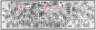
P200.png

Marked in red. It is extremely important to verify the four voltages in order to properly troubleshoot the IF strip. Make very sure you are presenting a strong FM signal, whether off-air, a cheapo MP3 FM transmitter or SG doesn't matter. All four voltages should be like the last one.

Having said that, 2.3 V across C213 is inconsistent with your symptoms (no tuning indicator deflection, low audio). Is H501 OK? DC-wise? C508?
 
Last edited:
Back
Top Bottom