• The move to the new server is done. There are some software and database maintenance updates in process. This has us passing the hat around to help out. We appreciate any donations. Seriously, even a dollar helps. The payment page may be found here - https://www.audiokarma.org/support.html

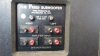
Fried Sub/Sat speaker system

Now the woofer....I'm not sure what it is. It has the following stamped on it: G620 and 1036, and 8920. Also 8 ohms. No manufacturer name. Any clues out there ? BTW, the satellites are heavy for their size. Just under 18lbs. each!!


Back of satellite mid/woofer. Any clue on brand ??


I think those are Eclipse woofers. (Construction looks the same) Seems to me I recall a long ago argument (pages of Speaker Builder?) that it was mentioned that Frieds woofers were made by that company. Irving disputed the notion that they were the same units as those sold to the public through Madisound and that those drivers used in Fried products were much higher performance. BTW, those TL designs are generally considered junk, and given the concern about landfills reaching their limit I think you you should send them to me for "proper" disposal..
 
I think those are Eclipse woofers. (Construction looks the same) Seems to me I recall a long ago argument (pages of Speaker Builder?) that it was mentioned that Frieds woofers were made by that company. Irving disputed the notion that they were the same units as those sold to the public through Madisound and that those drivers used in Fried products were much higher performance. BTW, those TL designs are generally considered junk, and given the concern about landfills reaching their limit I think you you should send them to me for "proper" disposal..

Hi Tom. Nice to see you make a rare appearance here on the AK forum.
 
Ohighway do you know if the previous owner was using the crossover?
Was he bi amping or tri amping all 3 drivers?

The former owner bi -wired the crossover for one thing.

If you want to run the speakers through the croosver don't connect to the bi amp terminals on the sub.. It is a liittle hard to tell the wiring layout of the crossover from the picture on the circuit board.


On the back of the satellites I would experiment running the [SUB OUT NEGATIVE] to the two [SATELLITE NEG] inputs.
 
Ohighway do you know if the previous owner was using the crossover?
Was he bi amping or tri amping all 3 drivers?


On the back of the satellites I would experiment running the [SUB OUT NEGATIVE] to the two [SATELLITE NEG] inputs.

No, he wasn't. However the previous owner was not the original owner. Hard to say what the original owner was up to.

I was thinking the same about hooking the SUB OUT negative to the -two- SATELLITE NEGATIVES, but hesitated because I wasn't sure if I might do any damage.
 
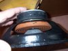
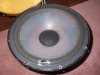
Pulled one of the 10" woofers today. Here's a few shots.

It's a very free moving unit with lots of excursion. Check the huge size of the spider.

Any hints on manufacturer? Model number ??

attachment.php


attachment.php


attachment.php
 

Attachments

  • 100_6473.jpg
    100_6473.jpg
    85.8 KB · Views: 168
  • 100_6478.jpg
    100_6478.jpg
    56.9 KB · Views: 166
  • 100_6475.jpg
    100_6475.jpg
    67.8 KB · Views: 139
Pulled one of the 10" woofers today. Here's a few shots.

It's a very free moving unit with lots of excursion. Check the huge size of the spider....

Wow OHigh, that looks well built!!! :yes:

I suck at this "guess the driver" game, so I have no clue. What seems interesting is it looks a little like the kind of Polyethylene driver that maybe Carbonneau was building? :scratch2:

Another thought I had... what drivers was Infinity using in the 80's? They had some Poly woofers in their systems!
 
Last edited:
The original oem Fried mid bass driver and the sub driver were made by Transparent Sound for the C2 and O2 models.
They went out of busniess and Fried later used Carboneau to source his woofers. Carboneau also went of business being bought out by Rockford Fosgate
The last version of the C and O models used Gefco to source his oem driver designs. These were the C6 and O6 1/4W T-lines.

Fried used double stacked magnets on many of his oem sourced drivers.
The magnet on the O2 sub driver is 120mm in diameter just like the O3-O6 sub drivers.

Enclose is a link to a picture of the O6 sub driver.
You can see the similiar motor structure of the O2 compared to the O6 driver.
The O2 drivers do not have a vented pole piece through the back plate like the Carboneau and Gefco drivers.


http://www.audiokarma.org/forums/album.php?albumid=911&pictureid=5697
 
So, the short answer is that the driver I have shown was manufactured by Transparent Sound?
 
So, the short answer is that the driver I have shown was manufactured by Transparent Sound?

Yes those are the original Transparent Sound sub drivers. you have in the O2 subwoofer enclosures.
.
The mid bass driver in each of the satellites you have are not the original Fried oem drivers.
 
The last version of the C and O models used Gefco to source his oem driver designs.

Yes those are the original Transparent Sound sub drivers. you have in the O2 subwoofer enclosures.

The mid bass driver in each of the satellites you have are not the original Fried oem drivers.

So assuming I have the C2 satellites and O2 subs:

1) Would the Scanspeak D2008 tweeters be consistent with my satellites being C2?

2) Would/could the Gefco mid bass drivers I have be Fried's replacements for the original Transparent sound mid bass drivers found in the C2?

3) You're saying the 10" drivers in the subs are Transparent Sound units correct for the O2? The schematic you sent me for the O2 lists the bass driver number as a T-8140. Mine is a T-7825.

I think I need a score sheet to keep up with all this.....:sigh:
 
The T on the back of the driver is for Transparent Sound.
I am not sure what the other numbers on the back plate of the driver signifies.

Yes the Scan Speak 2008 tweeter is correct for the later versions of the C2 model. The first C2 used the Dynaudio D-28H tweeter like the C1.

http://www.hometheaterequipment.com...gendary-speakers-70s-friedclassicspeakers.jpg

The Carboneau drivers were used after the Transparent Sound went out of business in the C3L enclosures.

He changed the C satellite enclosures from aperiodic to T-line loading around 1985-86.

Fried changed tweeters in the C3L model as well.
I heard an early C3L model which used the Scan Speak 2010.
Later models of C3L used the Hiquphon 2092 Fs.

I have stated numerous times the mid bass drivers in your C2 cabinets are not oem Fried drivers for the C2 model IIRC.

Fried started using double stacked magnets on all his TOTL drivers starting with the C2 and O2 models. He used only 1' voice coils on his 6.5' drivers.
The small dust caps were designed to extend the high frequencies of the mid bass driver. All of his mid bass drivers have a voice inductance of .3 -.5 mh.

All of his T-line 10" drivers have a Vas of 170-180 liters.
The Qts. is .22-.28 and a Fs of 22-26 Hertz approximately.

The crossover values you showed in your sketch are not the correct values for the C2 model.

I have the crossover plans for every C and O model the company used.

I live in the same area Fried once lived in. I met him when I was a teen back in 1978. I become a customer of his speaker part kits starting in 1979.

 
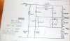
Cleaned up and combined my schematics and put them in a format the same as the Fried parallel schematic that I have.

I'm -assuming- the inductor values based on the Fried schematic. (Physical sizes of the inductors would suggest this is correct) Also, for the tweeter there's a couple caps that are unknown values (marked with H10000 and H15000 respectively) Until I disconnect and check them I'm not sure of their values.

Frankly I'm not sure I understand why the mid/woofer minus terminal is hooked into the sub crossover where it is. But then again I'm just trying to come up to speed understanding crossover schematics.

attachment.php


attachment.php
 

Attachments

  • MY Fried sub sat crossover.jpg
    MY Fried sub sat crossover.jpg
    61.7 KB · Views: 167
  • Fried parallel.jpg
    Fried parallel.jpg
    62 KB · Views: 219
Rick since I sent you the email I noticed on this diagram that you have drawn that the 200mfd capacatance is wired on the wrong side of the mid bass driver. It should have been wired on the positive side of the midbass driver.

There should be a 30mfd cap and 2ohm resistor in parallel of the subwoofer using the parallel crossover configuration.. Your diagram is bigger on this thread than the email.

I would rewire the crossover in the series configuration and replace all the caps and resistors.
 
:lurk:

Wow, you guys are getting into this and it really is interesting. I'm especially interested to see how these sound when Rick get's them wired correctly. Sounds like the PO's have muddled them a bit!
 
:lurk:

Wow, you guys are getting into this and it really is interesting. I'm especially interested to see how these sound when Rick get's them wired correctly. Sounds like the PO's have muddled them a bit!

Yes I want Rick to get them up and running as well. Using the correct crossover is critical in this endeavour.

The 1/4 W T-line sub enclosures are capable of reproducing some very natural sounding deep bass at high spl's..

I know those are Fried binding posts on the back of the speakers.
The PO may have modified them by placing the crossover on the back of the enclosure.

The assembled Fried speakers I have seen always had the crossovers inside the box.
The only exceptions may have been when Fried was designing the crossover for a new model ?
I know Fried had conducted demonstrations comparing the series crossover configuration to the parallel crossover configuartion for listeners.

I have wired crossovers outside of the box for design and testing purposes myself. I choose to put them inside of the enclosure when I have completed them.

My first parts kit for the model C had numbers and letters on the components. The cap, resistor and inductor values were not on the components.

Later speaker kits came with the enclosure and crossover plans showing all of the component values but not the crossover parts. The drivers without the damping material were also included. The wood for the enclosures had to be purchased, cut and constructed by the kit builder.

These were truly a DIY loudspeaker kit.

A copy of the series crossover plan is in the link.

http://s1297.beta.photobucket.com/u...pg.html?&_suid=136241060860506814088415448311
 
:lurk:

Wow, you guys are getting into this and it really is interesting. I'm especially interested to see how these sound when Rick get's them wired correctly. Sounds like the PO's have muddled them a bit!

Me too! One of the things that concerned me about picking these up was that I was flying blind. For all I knew all the drivers could have been incorrect replacements. But I made an educated guess and took a chance. It's not like these pop up every day, especially not within local driving distance.

I think they have potential for sure. Honestly they sound good but not quite right. I'm hoping that reworking the crossovers gets them where they need to be.

Yes I want Rick to get them up and running as well. Using the correct crossover is critical in this endeavour.

The 1/4 W T-line sub enclosures are capable of reproducing some very natural sounding deep bass at high spl's..

I know those are Fried binding posts on the back of the speakers.
The PO may have modified them by placing the crossover on the back of the enclosure.

The assembled Fried speakers I have seen always had the crossovers inside the box.
The only exceptions may have been when Fried was designing the crossover for a new model ?
I know Fried had conducted demonstrations comparing the series crossover configuration to the parallel crossover configuartion for listeners.

I have wired crossovers outside of the box for design and testing purposes myself. I choose to put them inside of the enclosure when I have completed them.

My first parts kit for the model C had numbers and letters on the components. The cap, resistor and inductor values were not on the components.

Later speaker kits came with the enclosure and crossover plans showing all of the component values but not the crossover parts. The drivers without the damping material were also included. The wood for the enclosures had to be purchased, cut and constructed by the kit builder.

These were truly a DIY loudspeaker kit.

Mine definitely appear to be DIY or kit built. Though IMO they did a good job of it. Hard to say what the thinking was on those crossovers but I will say at this point I'm happy that they're on the outside of the cabinet. Makes my life easier since I'm gonna' have to make changes.

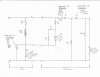
Speaking of changes, I regret to inform that I'd transposed my earlier notes incorrectly, and below is the corrected version of the crossover as it exists on my speakers. I had the 1 ohm resistor for the tweeter shown wired incorrectly. It is now corrected , and shown in parallel with the 2.22uF capacitance.

attachment.php


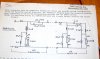
I'm also posting the Fried series crossover that Jim provided to me. Comparing the two, there seems to be some distinct similarity. Looks to me like the PO was aiming at a series crossover but maybe didn't get it quite right.

attachment.php
 

Attachments

  • MY Fried sub sat schematic rev 3-4-13.jpg
    MY Fried sub sat schematic rev 3-4-13.jpg
    62.9 KB · Views: 142
  • Fried series one.jpg
    Fried series one.jpg
    48.7 KB · Views: 198
I can't comment on the exact resitor value you should use to replace the resistor on the positive side of the tweeter circuit because of the different midbass driver.
Looking at picture of the crossover I think it is a 2 watt sand cast. Using sand cast resistors for the parallel resistors are fine.

http://meniscusaudio.com/resistors-lynk-c-92_64.html

I would purchase some Lynk or Mills non inductave wirewound resistors.
I prefer the higher watt rating of these over the sand cast.
For the price I would purchase several different values to experiment with.
I would try 1,1.5 and 2 ohms .

There have been many different opinions on what capacitors to use over the years on the forum. For the 210mfd cap value a good bypass polypropylene cap in combination with an electrolytic should sound fine.
 
20180207_121755.jpg 20180207_091957.jpg I had my Fried subwoofer driver out...coils came loose from the board..fastened with double stick foam tape. I cemented them down..good thing nothing shorted. Hope this helps someone.
 
View attachment 1109514 View attachment 1109515 I had my Fried subwoofer driver out...coils came loose from the board..fastened with double stick foam tape. I cemented them down..good thing nothing shorted. Hope this helps someone.

It might improve the sound if you replaced the electrolytic caps with new ones and used a small value poly bypass cap.
I can't read the value of the caps in the crossover?
Fried always used air core inductors in his crossovers and those appear to be 18 gauge.
 
Back
Top Bottom