
• The move to the new server is done. There are some software and database maintenance updates in process. This has us passing the hat around to help out. We appreciate any donations. Seriously, even a dollar helps. The payment page may be found here - https://www.audiokarma.org/support.html

Front End LO/RF Tracking and Alignment

PE9ZZ

Event Horizon
Subscriber
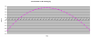
Some time ago I made a spreadsheet in order to optimize the tracking of the local oscillator and the RF circuits in an FM front end. The most interesting finding is that this alignment should not take place at the band ends (88/108 MHz) but rather at 90 and 105 MHz. In case of the well-known tuning diode BB204 the error curve looks like this:
bb204_tracking_error.png

The fun fact is that this is valid for any tuner. Whether varicap or capacitor tuned makes no difference. The only thing that changes things slightly is the capactiance variation of the tuning element. I made spreadsheets for a tuning capacitor I had in my junk box (28 pF), another one for a fictional tuning C of 15 pF and the abovementioned BB204 varactor. Every curve is the same parabola shape with zero points around 90 and 105 MHz.

Needless to say make sure to adjust the inductors at the low end and the trimmer capacitors at the high end. And first get the local oscillator to track with the tuning dial or the tuning voltage. You want the low end voltage to be as high as possible, usually around 3 V is a good target. This is because of the Q of the diode is low at low voltages. The BB204 should then end up with something like 15-20 V at 108 MHz.

Happy twiddling!
 

Attachments

Register to hide this ad
Whether varicap or capacitor tuned makes no difference.

Do you have some insight into why there would be a parabolic error curve with an old-school vaned capacitor? Wouldn't it be theoretically possible to shape the vane profile so that tracking would be perfect?

It's idle curiosity, really, since my usual practice was already to adjust tracking at frequencies similar to what you mention. I guess that is just because of an intuitive hunch that tracking error may be unavoidable at the extremes.

Thanks!
 
Interesting! As it happens I have been adjusting at 89.7MHz and 104.9MHz using actual stations at those points that are 30 - 40 miles away.
 
Wouldn't it be theoretically possible to shape the vane profile so that tracking would be perfect?
Some variable capacitors have splits in the end vanes so that you can do just that - reduce or slightly increase the capacitance by altering the position of the segments of the vanes. The capacitance increase or decrease is then dependent on the rotational position of the variable capacitor.
 
Wouldn't it be theoretically possible to shape the vane profile so that tracking would be perfect?
The error is only 0.1 MHz at most. Not enough to warrant shaping the LO vanes.

I was just frustrated I could never get an optimum while aligning a front end. Now I know why that is. If you adjust at a band end the opposite end will never get a perfect tracking. Also the part in the middle will be off much more. So, until someone proves otherwise this offset method is the best (and quickest!) way to align a front end.

Some variable capacitors have splits in the end vanes so that you can do just that - reduce or slightly increase the capacitance by altering the position of the segments of the vanes. The capacitance increase or decrease is then dependent on the rotational position of the variable capacitor.

The one in my junk box has solid vanes. I do have tuning capacitors with slotted vanes in the AM section. I'd wager these are used during production to conform to a linearity profile. While installed it would be near impossible to adjust.
 
Some radios used a padder capacitor in series with the variable one. It is claimed that the parabolic shape above changed to a sinusoid with three sero-axis crossings and much better tracking.
 
Some radios used a padder capacitor in series with the variable one. It is claimed that the parabolic shape above changed to a sinusoid with three sero-axis crossings and much better tracking.
This is actually true. The shape becomes a third power curve (f(x)=x³). I actually have an FM curve with a padder but it doesn't solve well because the frequencies are so close. The third zero crossing seems to be above the tuning range in this case. For AM it is a whole different story because the frequency variation is much greater. See attached spreadsheets. You will find that there is not much benefit of a padder at FM but it is essential at AM.
 

Attachments

Do you have some insight into why there would be a parabolic error curve with an old-school vaned capacitor? Wouldn't it be theoretically possible to shape the vane profile so that tracking would be perfect?

It's idle curiosity, really, since my usual practice was already to adjust tracking at frequencies similar to what you mention. I guess that is just because of an intuitive hunch that tracking error may be unavoidable at the extremes.

Thanks!

There have been some variable capacitors that were shaped with the centre of rotation off-centre to the vanes to stretch out the upper end of the scale. These are more commonly used on AM than FM where the FM range is smaller as a percentage of the spectrum. There have been accurate capacitors for constant wavelength change per degree of rotation and more extreme ones with constant frequency per degree of rotation but these are rarely seen. This does begin to throw doubt on the value of large numbers of gangs in a tuner (whether mechanically-tuned or varactor-tuned) because if you can't make them track, it makes matters worse rather than better.

Varactor diodes have an abrupt junction that makes capacitance variation follow the cube of the voltage whereas ordinary junction diodes follow the square of the voltage. Making a set of varactors track over the full range of the band (FM or AM) is a similar problem to making mechanical capacitors track.
 
There have been some variable capacitors that were shaped with the centre of rotation off-centre to the vanes to stretch out the upper end of the scale.

Indeed, I thought that was commonplace, at least since the time that it became de rigueur to have the front panel tuning scale be more or less linear.
 
Varactor diodes have an abrupt junction that makes capacitance variation follow the cube of the voltage whereas ordinary junction diodes follow the square of the voltage. Making a set of varactors track over the full range of the band (FM or AM) is a similar problem to making mechanical capacitors track.
I could not find anything in the BB204 datasheet but the BB909 (VHF varicap diode) datasheet boasts "Matched to 2.5%". This is prolly better than what can be achieved with a mechanical device like a multi-ganged tuning capacitor. Might be interesting to measure my four ganged device on my Wayne Kerr LCR meter.
 
Most of the old manuals that I've looked in call for 90 and 106 or so, not extreme ends of the band. Never really considered why but if it has an error curve that would make sense. I mostly mess with tube era stuff, so air core variable caps.
 
Indeed, I thought that was commonplace, at least since the time that it became de rigueur to have the front panel tuning scale be more or less linear.
Yes, that's right. The early FM tuners from the 50's - 60's had non-linear dials, and station numbering had no fine graduations, for many tuners was "approximate" on the dial. So they included a fine numeric dial as well underneath - the "logging" scale for h.h. scott round dial tuners, for instance.
Later tuners in the 70's had linear scales, and some were extremely accurate - the best Kenwood, Sansui, and Pioneer tuner from the mid to late 70's can be adjusted to better than 0.1 MHz across the dial. All that was no longer required in the 80's, with digital displays.
Bob
 
I just worked on a Sansui TU-9900, late seventies, and that thing tracked better than the pointer's width. Wonderful tuner. Only bummer is that they divided each MHz in four parts and not five.

Making an FM dial linear is not that difficult because the RF and LO are rather close together. AM (medium wave) dials are never frequency linear.
 
Do you have some insight into why there would be a parabolic error curve with an old-school vaned capacitor? Wouldn't it be theoretically possible to shape the vane profile so that tracking would be perfect?

It's idle curiosity, really, since my usual practice was already to adjust tracking at frequencies similar to what you mention. I guess that is just because of an intuitive hunch that tracking error may be unavoidable at the extremes.

Thanks!
I have wondered the same thing about actual station alignment on traditional tuners. Some, like the Mcintosh MR78 and the Marantz 10B are virtually perfectly linear. The MR71 has such a terrible non-linear dial that at the high end they inserted a "105" and "107" on the dial so it looks OK from five feet away.
 
Since we are talking about tuner alignments, is it possible to align a tuner without the service manual ? Because the B&K TS-108 and his siblings ( Fanfare ) there are not service manuals available anywhere.
 
Since we are talking about tuner alignments, is it possible to align a tuner without the service manual? Because the B&K TS-108 and his siblings (Fanfare) there are not service manuals available anywhere.
Really annoying, no manuals. I stay away from these devices. That said, yes, these rules are basic and apply to these tuners too. Will take some reverse engineering because you must understand what you are doing.
 
Since we are talking about tuner alignments, is it possible to align a tuner without the service manual ? Because the B&K TS-108 and his siblings ( Fanfare ) there are not service manuals available anywhere.

On tuner that are not overly complicated an experienced tech would be able to give it rough alignment, probably improve them. Most of the time you make out what is what without the procedure.
 
I have to disagree. A tuner front end is always the same. You must first identify the LO and all RF circuits. Then align everything. Not rough, optimal. If you cannot identify those sections, don't touch it.
 
I have to disagree. A tuner front end is always the same. You must first identify the LO and all RF circuits. Then align everything. Not rough, optimal. If you cannot identify those sections, don't touch it.

Stated experienced tech, An experienced tech can look at a front-end and would be able to tell which adjustments were the LO and which were the RF, if not they are not an experienced tech. Being experience they would know how to make those adjustments optimal, while maybe not following the manual. My advice was not for the layperson to go in and start doing rough adjustments. I was answering on whether or not an tuner could be aligned without a procedure.
 
That indeed is the caveat. Hence my comment about identification of those sections. A layperson would not be able to do that (but ask about it here).
 
Back
Top Bottom