• The move to the new server is done. There are some software and database maintenance updates in process. This has us passing the hat around to help out. We appreciate any donations. Seriously, even a dollar helps. The payment page may be found here - https://www.audiokarma.org/support.html

Fun with a 300DC someone else worked on

goldswimmerb

Failed out of engineering, but look at me now!
Subscriber
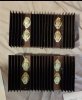
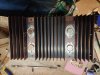
Hey guys, so I recently acquired a 300DC off of that auction site. Seller didn't disclose the fact that it had been worked on at some point. Looks like it got a full recap, but some of the work seems a bit shoddy and the cap selection almost seems random. Figured I'd ask here about what you guys think.

They at least used Nichicon Fine Golds for the filters:
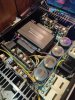
IMG_20200127_203544.jpg

However I am questioning some of the work, it appears that the cap selection was relatively random, for example using 85C UKZ caps in the PS which tends to run hot (they're buried and probably not visible in the photo), they did use UHE and SILMIC the bigger caps, which I'll probably leave, going to swap the UKZs out for some more appropriate UPWs. I also probably would've done Films for the 1UF. Probably going to replace Transistors and get rid of the dual diodes.
IMG_20200127_203606.jpg

My main concern was the amp boards,
Screenshot_20200129-191428.jpg Screenshot_20200129-191408.jpg

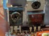
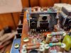
Aside from being a little toasted it appears one had a fairly traumatic experience at one point. Looks like the drivers were completely replaced though the replacement is proper, the Diff pair also looks new as do the tranistors near it.

Is it worth replacing that whole side with MJ21195/96?

I hate it when people don't replace the whole set as usually if half of the outputs blow the other two are next to go from what I understand. Though it may not be necessary since the original two seem to be fine.

Not sure why there's a random Wurth Cap in there, may swap it for consistency.

And I assume those aluminum polymer caps are fine, since my understanding is they're generally better than standard electrolytics.

I'll probably also go ahead and replace the blob diode since they're usually a liability.

Anything else I should do?
Is it worth it to replace all 4 outputs on that one channel?
 
Register to hide this ad
When someone's been in something I'm working on and it still has issues, 90% of the time I rip out all the crap they put in and do it my way.

It's worthwhile to have all outputs match on that channel. How you do that is your call.

I'd toss the al poly caps.
 
When someone's been in something I'm working on and it still has issues, 90% of the time I rip out all the crap they put in and do it my way.

It's worthwhile to have all outputs match on that channel. How you do that is your call.

I'd toss the al poly caps.


This one didn't actually have any issues, I bought it with the intent to rebuild anyway.
 
Is it just me or.......

Whenever seeing paste applied in such a fashion as this, all other work is now suspect.

I'll occasionally give a pass since thermal paste tries to get everywhere, but I do let it serve as a warning.

So far in the PS boards alone I've found a few poorly done solder joints.
 
So what I'm probably going to do is:
Pull all the caps on the amp boards, selection seems random, probably going to go for UPW in warmer areas and UKZ in what I can determine to be signal path.

Replace both channels outputs with new MJ21195/96 devices, I did notice FT and HFE Are lower on the MJs than the originals but I assume it won't be a problem.

I'll be leaving the drivers since his replacement seems to be adequate.
IMG_20200130_070345.jpg IMG_20200130_070314.jpg IMG_20200130_070241.jpg
Thermal paste is a mess but otherwise I don't see any issues.

Not going to swap drivers in the other channel since I don't think it's necessary to swap both. Though this unit was obviously run hot as can be seen by the darkening on the board around the drivers and differential pairs.

If anything jumps out at anyone else please let me know.
 
Amen to the first part that I dotted out. Out of curiosity and laziness to not go do research, why would you ditch those type caps?

From what I can see is they have lower ESR and better ripple, but higher leakage characteristics.
 
I've worked on plenty of PCs over the years which have had similar thermal paste / grease overloads. I've see the stuff hanging out from under CPU fans, all over the motherboards, splattered on the inside of the case etc etc. I've also seen (no lie) fingerprints of the stuff on a couple of monitors - how do people even manage to not wash their hands when working on this stuff?
 
Alrighty, so I went in and Replaced several components and cleaned up the thermal grease on the drivers.

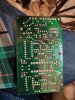
The back of the board was an absolute mess, looks like the last tech was just a dang trained monkey, actually invented a few new swear words when I saw it!!!
IMG_20200130_235129.jpg

I cleaned up his soldering a bit though it didn't come out too much prettier due to the extent of damage.

I replaced the Capacitors in warm sections of the board with UPWs and the two towards the edge of the board with UKZs since that section of the board seems to be cooler. Also replaced the MV-13 diode with 1N4148

The service manual was absolutely useless, or the guy used wrong value caps, but many Capacitor locations don't line up with the schematic, nor do several diode locations and a few resistors, not sure what happened there, I've never seen a Marantz stray this much from the schematic. For example C722/723 in this one were 22UF instead of 47UF, C711 didn't exist, C701 was unmarked, and just a significant amount of changes that threw me off.

I'm truly confused over C723 and C722, does anyone know if that was a factory change or if the guy working on this just messed up? I can't seem to trust the schematic.

Also the dude didn't even use thermal grease to bond the differential pair. Channel seems to be working nicely though, just waiting on those outputs. The drivers also run very hot though I think that's normal for this unit.

IMG_20200131_004649.jpg
I left the Wurth Cap in since it measured well and is rated for higher temps than my UFGs.
 
That beautiful heat shrinked and glued mess is 'factory work'.
I have no idea what they were thinking.

Tom
 
That beautiful heat shrinked and glued mess is 'factory work'.
I have no idea what they were thinking.

Tom

Wasn't worried about that, but more concerned about the wires he added to cover torn traces and lifted pads.

I went and replaced output Transistors today:
IMG_20200131_155304.jpg

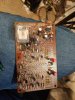
I also redid the relay board a bit, he messed up badly here too, lots of torn traces, broken relay cover, not sure why but it looks like he did his best to mess up every dang solder joint on the board... Also two of the replacement Capacitors appear to have been Ill suited, as they had already leaked.

IMG_20200131_163541.jpg

Anyway, I went and replaced the relay, put in 2 UPWS for the leaky 47UF caps previously installed, replaced the relay drivers and lifted them off the board due to heat, same for the relay diode as the board was darkened in that area. I also replaced the UFGs he used with WIMAs. And the double diode was replaced with a modern device as I've had bad luck with the original ones Marantz used.

IMG_20200131_172010.jpg
I went through and tried to clean up the mess made if the board where I could.


I also touched up the right channel PS a bit.
IMG_20200131_174236.jpg
Also, I noticed that when I was testing, the left meter was moving a bit too, is this normal? I had the left amp module removed when testing the right, so I'm guessing it was just bleeding over due to the left channel being "ungrounded" so to speak.

All that's left now is the left amp module, right PS board and those two 10UF caps hidden by the RCA Terminals.
 
This reminds me of the advice my dad used to give me when buying used cars - he's a retired mechanic with over 50 years in the industry. He used to always tell me to run away from a vehicle that looked like birds had crapped along the seam welds or if it looked like it had electrical work done by Spider Man.
 
That beautiful heat shrinked and glued mess is 'factory work'.
I have no idea what they were thinking.

Tom

Would there be any benefit to swapping the film Capacitors all over to WIMA? I noticed the previous guy working swapped them all out in one amp board, but left the other. It's been bothering me but I wanted to see if it actually matters.
 
Would there be any benefit to swapping the film Capacitors all over to WIMA? I noticed the previous guy working swapped them all out in one amp board, but left the other. It's been bothering me but I wanted to see if it actually matters.
I absolutely would match the boards.
Especially when comparing electrolytics to WIMA.
 
Back
Top Bottom