• The move to the new server is done. There are some software and database maintenance updates in process. This has us passing the hat around to help out. We appreciate any donations. Seriously, even a dollar helps. The payment page may be found here - https://www.audiokarma.org/support.html

Fun with MR71 detector: Replacing those Internal Capacitors!!

I have purchased the official Johnson and Johnson baby powder with vitamin E and aloe, but no talc and will gently dust the top and bottom of T1, T2, T3, and T4. And now I have the Sencore SG165 adjusted to 0.00003 percent, very very close to the theoretical ideal of 10.700Mhz. Will signal inject at pin 7 of the 12AT7 tube and read the output voltage at test point 1 and try to optimize for a maximum negative voltage on the Fluke. Initial impressions using the IF rocker is that many of the transformers are close but not dead on at 10.7Mhz. I have no idea if that messes up the 19Khz pilot along with the 57Khz passband.
 
I found the SCA on top of the chassis and it has red, orange, and brown wires. Orange to red and brown to red capacitor analysis is a short on the Fluke and B and K. Need to take the shorts out of circuit.
 
Wow C71 is defective also. It measures 100 times lower than spec. This controls the 19Khz oscillator!
 
Last edited:
I know this tread has some age on it, but as to the original subject of this thread, I too have had significant experience with the discriminator transformers in Mac vacuum tube FM gear -- having rebuilt a number of them as well.

Early on when I first started repairing these, like the OP, I also measured the original Primary Resonance and Secondary Coupling Caps (the ones built into the base of the transformer), finding them to measure 33pF and 35 pF much like the OP did. However, for those who may still reference this thread in the future, I can tell you that the transformer (transformers for those models with narrow and wide band discriminators installed) will not operate properly when discrete components of those values are installed to effect repair. Invariably, the slug in the primary coil will end up bottoming out when attempting to find a peak for that coil, while the secondary coil will still null to 0 when the primary slug is bottomed out, but these values will not allow for optimum performance of the transformer. This is important because the discriminators that Mac used are of the balanced phase shift type, which unlike the more common ratio detector types of the early stereo years, will detect AM as well as FM signals, so optimum peaking/nulling is important to ensure maximum limiting/minimum noise in the output.

Because these two cap are effectively in parallel with the primary winding (one directly so), it will be found that using discrete values of 18pF for each of these caps (basically half of their measured value) will return the transformer to optimum efficiency, as well as the slugs of both coils basically to their normal locations, allowing each to easily and properly be peaked/nulled as required. Of the nearly one dozen of these transformers I've serviced over the past 35 years, these values have always returned the transformers to normal operation. The wide-band detector in my MR-65 (w/MA-5 adapter) started acting out as well the other day, and once again, disabling the internal base mounted caps and replacing both of them with external 18 pF discrete caps returned the transformer to normal operation, with the slugs requiring little change for proper peaking/nulling, and plenty of adjustment range for both slugs if needed.

I hope this helps those in the future who take this type of work on. It is tedious work no doubt, but Mac gear is worth it, and when finished, you'll never have an issue with the transformer again!

Dave
 
Hi,

new to this forum, I came across this interesting thread whilst repairing and aligning my MR71.

I repaired it by changing the oscillator tube. Then I began to realign everything but had problems bringing the discriminator within specs, distortion-wise. I had the impression that sometimes, without merely touching the unit, the discriminator alignment settled with brilliant specs (less than 0,1% with 400Hz@75kHz), just to go back to 1-2% of distortion at the next warmup.

Could that be the mentioned Mica capacitor problem? I might solder 18pF on the tank sockets to see if this changes things to the positve side...
How do you remove the tank case? There are latches on the side and the bottom I don't want to break.

cheers
Martin
 
Welcome to the AK Mac forum!

That's certainly one of the classic indicators -- not holding the adjustment setting. If you're sure that your generator is stable, then the discriminator transformer is the obvious suspect. It is usually best however to change both caps, as either or both could be the culprit. You've got to unsolder, unclip, and remove the transformer to repair it, as the internal caps must be disabled from the circuit.

Dave
 
Welcome to the AK Mac forum!...

Thanks for the warm welcome, Dave!

Yesterday I tried soldering 18pF caps at the lugs that correspond to one of the internal caps (supposing its only one that is bad). That wasn't conclusive - I measured some drop in level, but the primary still behaves similar. In fact, I get the max when the primarie's slug is on the very bottom, i.e. with minimum inductivity. Doesn't that mean the LC resonance is too low? So instead of rising resoncance frequency, adding capacity would make it even lower?

As a last try before doing the internal replacement I was thinking of swapping T5 and T6. They have the same part number, so they should be identical. And T5 seems to behave as it should.

Aligning the IF circuits gives me a nice curve at TP1 with an RF signal of 5uV at generator output (its a formidable HP8645A, out of a trash bin and took me many weeks to repair). The generator is sweeping 1MHz around 100MHz, and is hooked up to the 75Ohms antenna input via a 75-50-Ohms adapter, so the input level at the MR71 is 5-6dB lower. I check IF frequency with a spectrum analyser, also hooked up to TP1.

When the RF level is ramped up beyond something like 50uV the curve is getting very asymmetric. Not sure if this means anything, everyone says alignment has to be done at low levels. But it could be a source of distortion although the limiter stages might level this out. BTW, tubes have been checked and even compared with a NOS replacement. Diodes check good. I might check the remaining passive components, but all that I tested so far were good.

I'll do some more measurements of IF curves, and post the screenshots...

cheers
Martin
 
I checked the components again, so far nothing is wrong, all diodes checked out good. Forward voltage of all 4 is around 0,6V - I would have expected less as these are germanium diodes, I suppose.
HF voltages and shapes on D5 are comparable to D4 and D5, whereas D6 gets only about half of that.

Before unsoldering the transformers I made an alignment of T5 and T6 for minimum distortion, as T5 had a notable influence. I came out at 0,1-0,2% (1kHz) for all RF levels above 3uV, with an alignment of T5 quite a bit off compared to the usual method. Unfortunately, distortion deteriorates quickly when the dial is somewhere else on the scale. It quickly raises to 1-2% at the respective ends of the scale. This is not normal behaviour, what do you think?

cheers
Martin
 
The deterioration of the oem silvered mica resonance caps in the bottom of the cans makes for unstable function.
 
The deterioration of the oem silvered mica resonance caps in the bottom of the cans makes for unstable function.
You mean the fact that I get higher distortion on other RF frequencies (other than the 100Mhz where I aligned the detector for minimum distortion) is due to a deteriorated mica in the detector stage?

How can that be... there should be no difference of a 90MHz and a 100MHz station as seen by the detector! Both stations should give a 10,7Mhz signal at the end of the IF amp with the same shape when the RF frontend works as it should.

How do other FM tuners behave? Do they usually give same distortion all over the RF range?

cheers
Martin
 
You mean the fact that I get higher distortion on other RF frequencies (other than the 100Mhz where I aligned the detector for minimum distortion) is due to a deteriorated mica in the detector stage?

How can that be... there should be no difference of a 90MHz and a 100MHz station as seen by the detector! Both stations should give a 10,7Mhz signal at the end of the IF amp with the same shape when the RF frontend works as it should.

How do other FM tuners behave? Do they usually give same distortion all over the RF range?

cheers
Martin
Honestly do not know for sure, tho alignment can be unstable with the condition occuring in one or more of the cans.
Others have much more experience dealing with these things and their fault modes, I quit fooling with them when not having an alignment bench became an obstacle due to the silver mica problem.
 
Ap -- You're certainly using good equipment. I use the HP 8640B, which has been superb for all my alignment needs.

The levels are always instructed to be as low as possible to keep the limiters from limiting -- otherwise their adjustment becomes worthless. Of course that won't affect any monitoring at TP1 since it occurs before the limiters.

As a basic premise however, you are absolutely spot on -- the distortion should change with received frequency -- unless something is going on at the transmitter end. You might verify that distortion remains low relative to received frequency with another known tuner/receiver of good standing. I don't think I've ever checked the distortion level at the output of the discriminator in my MR65 (basically the same tuner for this discussion) at anything other than 100 MHz. But either way, distortion should be unchanged -- although, since all audio begins at the audio discriminator transformer, what else could it be? It's acting like there is a shift in the detector curve with (possibly) the slightest change in IF frequency (or possibly amplitude?). It's a strange one to be sure.

I've found it to be the secondary coupling cap that gives the most problems -- so far, it sounds like you've only played with the primary shunt cap. As I recall, when either of the caps are too big, it causes the primary slug to bottom out for best performance -- although it is performance that is still well off optimum. This goes directly back to my post #46, where I found basically through experimentation that 18 pF was an optimum value for the two caps, and returned performance virtually identical to that of the original caps when good.

Keep us posted!

Dave
 
Hi Dave,

before unmounting T6 I removed all components from T6 AND T5 and compared them. To my surprise they turned out to behave very much the same (comparable max, range and Q)! Only once I saw the max of T6-primary jumping some 2MHz higher. I guess thats it, so I took the filter out and the cap off.

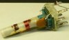
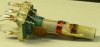
But now what? I can't find any mica, just a usual ceramic 33pF. They must be totally hidden in the base. Can you or anybody else provide some guidance how to continue from there? I couldn't find any pics of these filters, so I made some myself. Maybe that will help someone else, too.

Keep us posted!
I certainly will!

cheers
Martin

P1370991 (08.12.2021 - 17h14).jpg
P1370992 (08.12.2021 - 17h14).jpg
P1370994 (08.12.2021 - 17h15).jpg

P1370995 (08.12.2021 - 17h15).jpg

P1380002 (08.12.2021 - 17h18).jpg
 
Last edited:
Hi Ap -- The caps are in fact built into the base of the transformer.

I have fixed a number of IF transformers and discriminator transformers, and the fix depends on the function of the transformer, but what I usually do (and did in this case) with discriminator transformers is to first disconnect the primary coil lead from terminal 3. Then I manage to break off and pull out the cap plate from between the layers that's connected to terminal 3 as well. This last effort is necessary to ensure that there is no longer any coupling between the two internal caps. Then I cement in a new terminal in the unused #5 position, made out of #14 pr #16 gauge solid copper wire. I connect the primary coil wire removed earlier to it, and then reassemble the transformer, making sure the new terminal is not shorted to the can. Now you have a transformer with just the secondary cap in place. Reinstall the transformer, and add the new primary and secondary coupling caps externally.

Dave
 
I had a better look at the filter under a magnifying glass. There is something that looks like a sheet of mica between terminals 1+2 and 3+4, held by the contacts agains top or bottom of the socket. I could not make out the coupling capacitor, although there is a connecting line between terminals 3 and 6. The ceramic 33pF is connected across terminals 1+2, but what for? Has the internal mica broken during manufacturing? Its not even an NP0, but it looks all original.

cheers
Martin
 
I had a better look at the filter under a magnifying glass. There is something that looks like a sheet of mica between terminals 1+2 and 3+4, held by the contacts agains top or bottom of the socket. I could not make out the coupling capacitor, although there is a connecting line between terminals 3 and 6. The ceramic 33pF is connected across terminals 1+2, but what for? Has the internal mica broken during manufacturing? Its not even an NP0, but it looks all original.

cheers
Martin
The deposited silver tarnishes, and it otherwise deteriorates in various ways, "whisker" shorting, migration, ect. What seemed like a good idea came with negative unintended consequences, discreet npo shunt caps would have been a much better approach.
 
Last edited:
Hi Pio, Dave,

many thanks for the link and further insight. I start seeing clearer now. So the sheet of mica I'm seeing is not the capacitor but just an isolation. And there are only 2 caps in the base, not 3. Why is the ceramic disc type cap not an NP0? There is a comparable NP0 connected to the terminals...

Drilling out the rivet, braking terminal 3, I have to think about it. And there is the initial thread using Deoxit + compressed air which sounds promising. If it doesn't work I can still do one of the others.

cheers
Martin
 
Back
Top Bottom