• The move to the new server is done. There are some software and database maintenance updates in process. This has us passing the hat around to help out. We appreciate any donations. Seriously, even a dollar helps. The payment page may be found here - https://www.audiokarma.org/support.html

Futterman H3aa monoblocks restoration

Back! Mom's doing better. Spent the evening checking resistors because YOU GUYS ARE MEAN. Almost all in spec. One or two obviously bad, and another couple that probably are but I need to get them out of circuit to be sure.

So okay. Fine. It was the right thing to do.

Caps get here midweek! Woooooo!!!
 
The voltages for each cap section are usually on the same line as the capacitence, just out of sight in the photo. The 218 and the letters after are probably a manufacturing code.
Hmmmm, that's a good flag. I'll see if I can pull one or get a different angle.
 
Back at it. Pulling those suspect resistors. Can you all help me confirm the value of this little guy? It was in parallel with a 1.5k ohm resistor between the big speaker cap and the input.

That resistor is frakked so will be replaced. The hollow one looks to me like black-brown-purple-red = 1.7k ohm.

IMG_4603.jpeg

IMG_4604.jpeg
 

Attachments

  • IMG_4605.jpeg
    IMG_4605.jpeg
    289.3 KB · Views: 3
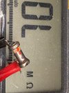
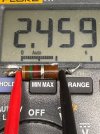
Ok so what I think we're dealing with here is a 1.7kΩ hollow wirewound in parallel with a 1.5kΩ carbon comp (which measured at 2.5kΩ!) for a total 797Ω resistance. I went with a single 820Ω 2W film that measured at 815. That a 32Ω difference or 4% of 797. I can live with that. Shout if you think different.
 
1781179924402.png
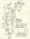
schematic, assuming its at least in the neighborhood of accurate, are we talking about C14 and R26? If so its calling for 1.5K resistor and 270pF of cap.

that dot code is a bit strange, not sure what the leading orange is, unless thats one of those "color dot indicates dielectric type" things. Sometimes the domino caps were marked that way.
 
Well sheeeeeeee-it. You nailed it.

Also where did you find that schematic? I thought I'd done a thorough Google search and I came up with nada. THANK YOU!
 
it was the first hit on Google for "Futterman H3AA schematic"


thats the H3A, there is a reply to it with the H3AA
I HATE how Google has broken its search to force people into using the AI. That result doesn't come up for me even on the first three pages using that exact search term.
 
After some hiccups, we have full, stable power-on with all tubes and 8Ω dummy load on one channel. Woooooooooo!

Updates
  • Recapped and out of spec transistors replaced on one channel.
  • I bought a B+ filter cap thinking I just wanted to get it working and that the aesthetics wouldn't bother me. Now that it's here and replacing the can I hate it. Maybe it will fit inside the can? It does indeed slide in nicely -- for the first 1/4". Then the can narrows just a tiny bit and... no. GRRRRR. This will wait for later but I may go the Heyboer route (depending on cost).
  • Slowly brought up on a variac and.... one of the banks of the output tubes redplated. Ok. Shut down. Reexamine. Found a mistake in the wiring that I made when reattaching some leads. (Thank goodness for a second reference channel.) That's now fixed.
  • Also found two places in the reference channel where connections were made with the tiniest wisps of wire that were missing in the one I'm working on. Added those in.
  • Tightened loose receptacles on one of the tube sockets. Only one out of 12 was even a little loose. Not bad for 51 years!
  • Checked the bias pot which I should have done in the first round. There are 3 or 4 spots where it shows no reading or open. No change after DeOxIt. It was stable and smooth outside those spots so I just left it close to the highest resistance value and didn't touch it when powering up.
Questions

Disclaimer: I don't have a schematic for this and I'm not sure there's one to be found. The one gadget posted earlier in this thread is more like the inspiration for what I have in front of me.
  • Should I suck it up and try to write out the full schematic? I've never done that before and suspect my drafting would be, well, bad. But I suppose I should for posterity if nothing else. Please someone help and tell me that no no no there's no reason at all to do that. Someone...?
  • Replace bias pot altogether? I'd like to keep these as original as possible but not to an irrational degree. If there's something sensible to do to the existing pot I'd prefer to try but if not I'll replace.
  • What's with the wisps? I mean one small copper filament, smaller than a single strand of speaker wire. I did replace with a single strand of speaker wire since that was the smallest diameter I had on hand. Is that potentially a problem?

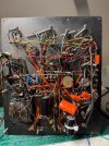
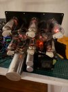
IMG_4786.jpegIMG_4787.jpeg
 
depending how different the schematics are, maybe just modify the one thats closest ? Sometimes thats more work than just drawing the whole thing fresh though.

I don't really know much of anything about these amps but the little I have read makes me think they were being tinkered with fairly regularly. Its entirely possible that fully accurate schematics for each variant just don't exist. I also don't get the impression these were ever made in high volume.
 
depending how different the schematics are, maybe just modify the one thats closest ? Sometimes thats more work than just drawing the whole thing fresh though.

I don't really know much of anything about these amps but the little I have read makes me think they were being tinkered with fairly regularly. Its entirely possible that fully accurate schematics for each variant just don't exist. I also don't get the impression these were ever made in high volume.
Yes I think I might start with the one you found and try to modify it. That might make things easier.

Definitely low volume! Hand made in Futterman's NYC apartment from what I understand. And it turns out this is the very first pair he ever made. #1A and #1B! Which could complicate things depending on whether the schematic you found is an early design or a later mod/update.
 
ah yeah the later schematics probably have updates or improvements that this pair lacks. Or maybe if he kept this pair, they might have been development mules that got things that others did not.

Pretty cool bit of audio history though being the first set.
 
Back
Top Bottom