• The move to the new server is done. There are some software and database maintenance updates in process. This has us passing the hat around to help out. We appreciate any donations. Seriously, even a dollar helps. The payment page may be found here - https://www.audiokarma.org/support.html

Futterman H3aa monoblocks restoration

Jfaustus

AK Subscriber
Subscriber
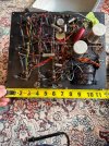
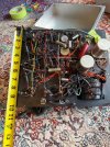
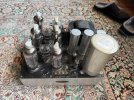
I am the proud new owner of a pair of Futterman H3aa output transformerless monoblocks. These were from the estate of Doug Cassara, who when he was young was Futterman's assistant. They were built in 1974, I believe, based on the markings on the underside of one board (including what appears to be Futterman himself initialing one of them). And owned by Doug since 1977 (he etched his name, address, "second owner" and the date on the inside of the bottom of the chassis). They look very much like they haven't been run for decades.

Fully point-to-point wired. Nary a PCB to be found (the board referred to above is the metal top plate -- everything is wired to this. Sockets and can caps on top wiring on the bottom. Nothing attaches to the chassis.

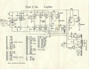
I have been able to find very little information about these on the online. But here's what I know or can conjecture so far. Feedback and corrections welcome!
  • Mono version of the same circuit as the more well-documented H3.
  • Each channel has a complement of:
    • Six 6LF6 output tubes
    • Two 6LR8 driver tubes
    • 6EJ7 Input
    • 6FS5 phase splitter
  • Both channels have a socket for an OC2 for bias. One has the tube present the other doesn't. Both units appear to have an updated bias circuit using a 1N2484 zener diode. I read somewhere that this was a known design change.
  • Both power xformers test correctly for resistance across primary and secondary windings.
    • There are two heater supplies from two secondaries that are isolated from one another.
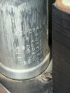
  • B+ rail probably runs at about 200V -- the 720uf (ish) worth of caps on there are rated at 218V so that's an upper limit.
  • Big cap (2500uf 350V) appears to be the speaker coupling cap.
All the tubes on tested "good" on my EICO 667 except for one 6LF6 where the tiny top part with the lead opened up and let the vacuum out. I also have a Hickok 600A but alas no compactron adapter.

Plan. Please shout if you see anything missing or not right.
  1. For sure replace the B+ caps. These are odd ducks in that each unit has three multisection can caps, 200/30/4/10 218V -- all three paralleled together. So basically functioning as one 732uf cap. I also don't love how close they are to what I think is the B+ voltage. So I'll go higher there. Is there any reason at all to NOT replace all these with a single 800uf 385v cap? Maybe there's some advantage to using many caps/sections I'm unaware of? I'll be able to fit a replacement inside one of the three cans and clip the leads of the rest to keep the original cosmetics.
  2. There aren't that many other caps.
    • Some of the other, smaller, ones look unhappy in one channel so out they go, to be replaced in both for symmetry.
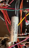
    • The ones I really want advice on are the coupling caps from the input to output stages. These are 0.22uf. They're Sprague, silver colored -- electrolytic? I'm tempted to replace them with fancy film.
    • I've reformed one of the big 2500uf speaker caps and it tests very much in spec on a Sencore LC103 at rated voltage. Assuming the other one performs similarly I would -- I think -- prefer to keep them. But if that's a really bad idea I also happen to have in the parts bin a pair of BC (not Philips not Vishay so probably made between 1998 and 2002) that are rated at 2200 but test at 2500 and test good for leakage. And there are new manufacture Nichicon LNK2G272MSEH that's a drop-in replacement (same size; 2700uf 400V).
  3. Buy a few 6LF7s to replace the broken one and have some spares.
  4. What do we think about replacing the bridge rectifier? It's a 600V 25A, 1.1V forward voltage. Given the timeframe it's very likely to be an early silicon diode rectifier.
  5. Not sure I need to check each and every resistor. Thoughts? I've spot checked several and all have been in spec. No observable heat stress near any of them.
  6. Clean, clean clean -- chassis, pots, tube sockets.
  7. Bring up on variac without tubes and see what's what. Assuming all is dandy...
  8. Add tubes and load, set bias and balance. This is a whole 'nuther discussion that will be had when I'm closer.
  9. Build a wooden case.
Pics, including nudes of the less stressed channel. The tape is where I secured the leads next to the poles of the big cap when I removed it for testing.

IMG_4506.jpeg

IMG_4565.jpeg

IMG_4552.jpeg

IMG_4553.jpeg
 
Last edited:
Register to hide this ad
There is an argument to be made for slightly lower ESR with parallel sections, but I strongly suspect a modern 800uF cap is at least as good as whatever the original clocked in at. +1 on bumping the voltage.

218v is a really weird value too. Might want to confirm that, I've never seen a cap at that specific a voltage before.

An 0.22 cap is unlikely to be electrolytic. Have a series or part number? Could be some type of film or maybe even PIO. I can't make out the markings, pic got resized and it just blurs if I zoom on it. I see white ends but I can't work out if its plastic or a glass end seal. I don't know that they are anything special but they may be just fine.

I've not had a lot of problems with silicon, and this is easily a decade into their use so not that early. Replace if you like, but its probably fine.

Being carbon resistors I'd check them all in circuit at least. They have a tendency to drift, though those look like the better quality ones so you may be fine here.
 
@gadget73 you're one of the people I'd hoped would show up in this thread! Welcome. And thanks for the input. Here are some closeups of the caps in question.

IMG_4532 2.jpeg

IMG_4523.jpeg
 
sure looks like 218v, what a weird value

Those Sprague caps sure look like they have glass end seals, which I normally associate with sealed paper in oil caps. Or at least the one in the lower left corner sure looks like a glass seal. Still cant read the string of numbers to see if there is a series or type or something to confirm though. I have seen mil spec wet tantalum caps that look awful similar to PIO types too. also seems like an odd choice for coupling but who knows.
 
EDIT: Based on the excellent info on this thread, these are Vitamin Q or a related line of Sprague PIO caps.

The rest of the markings on the 0.22 cap are: 188P2240252, 3DA220-9.

Funny fact (well, factoid): according to several sources, Futterman used whatever surplus he could get his hands on for the B+ caps -- including ones designed for photography flashes. These released their voltage SUPER fast and may have contributed to some of the early reputation for unreliability.IMG_4548.jpeg
 
Last edited:
Agree with gadget73 on the Sprauge 188P oil caps. Keep them.
What value are the output caps? I’d be thinking about some modern capacitor technology like Electronic Concepts film Unipolar caps. My former father in law was production manager for EC so I have some high-end caps I was able to buy at distributor cost a few years back. If you want to try some let me know and I’ll see if I have anything suitable on hand.
Peace,
DrRick
 
Agree with gadget73 on the Sprauge 188P oil caps. Keep them.
What value are the output caps? I’d be thinking about some modern capacitor technology like Electronic Concepts film Unipolar caps. My former father in law was production manager for EC so I have some high-end caps I was able to buy at distributor cost a few years back. If you want to try some let me know and I’ll see if I have anything suitable on hand.
Peace,
DrRick
The output caps are 2500uf 350V!
 
The Spraugues are vitamin Q types. They should be good as they are hermetically sealed- buy hey - there is always no accounting for taste on coupling caps. On the the big isolation cap and PS caps --modern equivalents should be better in every regard.

I have a pair which are a later date mfr. probably late 80's early 90's they use photo flash caps for decoupling and isolation from the speakers... I will end up changing those and have been working on some ideas for this
 

Attachments

  • IMG_6331.jpeg
    IMG_6331.jpeg
    157.8 KB · Views: 49
The Spraugues are vitamin Q types.
Thanks! I will be leaving them in.

And I’ll just go ahead and get new speaker isolation caps. I think I’d prefer peace of mind at that particular spot in the circuit…
 
maybe not the worst idea, could also do a speaker protection board like would be used on solid state amps to disconnect them if any DC gets through. One of those could be done in an external box easily enough.

provided the cap is good though I think you're probably fine. Lots of cap coupled solid state amps exist and aren't considered a concern for speakers melting.
 
EDIT: Based on the excellent info on this thread, these are Vitamin Q or a related line of Sprague PIO caps.

The rest of the markings on the 0.22 cap are: 188P2240252, 3DA220-9.

Funny fact (well, factoid): according to several sources, Futterman used whatever surplus he could get his hands on for the B+ caps -- including ones designed for photography flashes. These released their voltage SUPER fast and may have contributed to some of the early reputation for unreliability.View attachment 3770564
The problem with oil filled caps is they tend to pass a slight amount of DC Voltage. That can throw off the operating point of a tube, so Bad Things can happen. I'd replace them with a proper film cap. I had to replace a bunch of Vitamin Qs in an amp recently as they were all leaking oil...

There's nothing special about the carbon comp resistors. Check them to make sure they are what they say they are. I recently restored an amp that was NOS, never used and some of the carbon resistors had drifted, with no use at all, by as much as 50%. They were about 15 years older, so there's that but who knows how many of the parts Futterman bought surplus.

BTW the photoflash caps seen in some later Futterman amps was something Harvey Rosenburg did. He bought them surplus from Bill Godbout Electronics. Being surplus, and also unable to handle high ripple currents, they were unreliable. Harvey peeled the covers off of them so he could sell the amps in the Japanese market. With the covers removed they did not look like the Rubycon parts they were.

Just replace the output coupling cap. New parts have so much better performance its unlikely bypassing it will do anything to affect bandwidth.

Go through the amp and make sure all the tubes have proper grid stop resistors. Futterman OTLs tended to have a lot of feedback so inherent stability is pretty important.
 
Ah Rosenberg, he was also involved with New York Audio Labs, who made the Miscode stuff. I have one of their preamps. Sounds good, no documentation to speak of, and not great construction. Had a hell of a time getting that thing quiet with all of the bad solder and cracked traces.

I think George Kaye was the designer on that stuff
 
The problem with oil filled caps is they tend to pass a slight amount of DC Voltage. That can throw off the operating point of a tube, so Bad Things can happen. I'd replace them with a proper film cap. I had to replace a bunch of Vitamin Qs in an amp recently as they were all leaking oil...

There's nothing special about the carbon comp resistors. Check them to make sure they are what they say they are. I recently restored an amp that was NOS, never used and some of the carbon resistors had drifted, with no use at all, by as much as 50%. They were about 15 years older, so there's that but who knows how many of the parts Futterman bought surplus.

BTW the photoflash caps seen in some later Futterman amps was something Harvey Rosenburg did. He bought them surplus from Bill Godbout Electronics. Being surplus, and also unable to handle high ripple currents, they were unreliable. Harvey peeled the covers off of them so he could sell the amps in the Japanese market. With the covers removed they did not look like the Rubycon parts they were.

Just replace the output coupling cap. New parts have so much better performance its unlikely bypassing it will do anything to affect bandwidth.

Go through the amp and make sure all the tubes have proper grid stop resistors. Futterman OTLs tended to have a lot of feedback so inherent stability is pretty important.
Thanks! That makes sense. Wondering — are you Ralph K?
 
Away from this for a bit while I'm on the road helping my mom recover from surgery. Components on order! When I'm home I'll test all the resistors, install the new caps, and we'll see what's what.
 
Back
Top Bottom