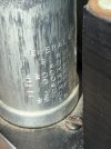
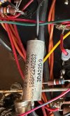
I am the proud new owner of a pair of Futterman H3aa output transformerless monoblocks. These were from the estate of Doug Cassara, who when he was young was Futterman's assistant. They were built in 1974, I believe, based on the markings on the underside of one board (including what appears to be Futterman himself initialing one of them). And owned by Doug since 1977 (he etched his name, address, "second owner" and the date on the inside of the bottom of the chassis). They look very much like they haven't been run for decades.
Fully point-to-point wired. Nary a PCB to be found (the board referred to above is the metal top plate -- everything is wired to this. Sockets and can caps on top wiring on the bottom. Nothing attaches to the chassis.
I have been able to find very little information about these on the online. But here's what I know or can conjecture so far. Feedback and corrections welcome!
Plan. Please shout if you see anything missing or not right.
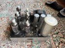

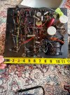
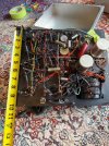
Fully point-to-point wired. Nary a PCB to be found (the board referred to above is the metal top plate -- everything is wired to this. Sockets and can caps on top wiring on the bottom. Nothing attaches to the chassis.
I have been able to find very little information about these on the online. But here's what I know or can conjecture so far. Feedback and corrections welcome!
- Mono version of the same circuit as the more well-documented H3.
- Each channel has a complement of:
- Six 6LF6 output tubes
- Two 6LR8 driver tubes
- 6EJ7 Input
- 6FS5 phase splitter
- Both channels have a socket for an OC2 for bias. One has the tube present the other doesn't. Both units appear to have an updated bias circuit using a 1N2484 zener diode. I read somewhere that this was a known design change.
- Both power xformers test correctly for resistance across primary and secondary windings.
- There are two heater supplies from two secondaries that are isolated from one another.
- B+ rail probably runs at about 200V -- the 720uf (ish) worth of caps on there are rated at 218V so that's an upper limit.
- Big cap (2500uf 350V) appears to be the speaker coupling cap.
Plan. Please shout if you see anything missing or not right.
- For sure replace the B+ caps. These are odd ducks in that each unit has three multisection can caps, 200/30/4/10 218V -- all three paralleled together. So basically functioning as one 732uf cap. I also don't love how close they are to what I think is the B+ voltage. So I'll go higher there. Is there any reason at all to NOT replace all these with a single 800uf 385v cap? Maybe there's some advantage to using many caps/sections I'm unaware of? I'll be able to fit a replacement inside one of the three cans and clip the leads of the rest to keep the original cosmetics.
- There aren't that many other caps.
- Some of the other, smaller, ones look unhappy in one channel so out they go, to be replaced in both for symmetry.
- The ones I really want advice on are the coupling caps from the input to output stages. These are 0.22uf. They're Sprague, silver colored -- electrolytic? I'm tempted to replace them with fancy film.
- I've reformed one of the big 2500uf speaker caps and it tests very much in spec on a Sencore LC103 at rated voltage. Assuming the other one performs similarly I would -- I think -- prefer to keep them. But if that's a really bad idea I also happen to have in the parts bin a pair of BC (not Philips not Vishay so probably made between 1998 and 2002) that are rated at 2200 but test at 2500 and test good for leakage. And there are new manufacture Nichicon LNK2G272MSEH that's a drop-in replacement (same size; 2700uf 400V).
- Buy a few 6LF7s to replace the broken one and have some spares.
- What do we think about replacing the bridge rectifier? It's a 600V 25A, 1.1V forward voltage. Given the timeframe it's very likely to be an early silicon diode rectifier.
- Not sure I need to check each and every resistor. Thoughts? I've spot checked several and all have been in spec. No observable heat stress near any of them.
- Clean, clean clean -- chassis, pots, tube sockets.
- Bring up on variac without tubes and see what's what. Assuming all is dandy...
- Add tubes and load, set bias and balance. This is a whole 'nuther discussion that will be had when I'm closer.
- Build a wooden case.
Last edited: