• The move to the new server is done. There are some software and database maintenance updates in process. This has us passing the hat around to help out. We appreciate any donations. Seriously, even a dollar helps. The payment page may be found here - https://www.audiokarma.org/support.html

G-7700 near-basket-case where to start?

Although eBay is pretty popular because of extreme growth, I believe their policies are making it less attrtative for both buyers and selers. As such there is a new policy. Item will be photographed as it is packed to prove the packing is adequate. Buyer will cooperate in cae of damage and that means sending pictures of the damage. Buyer is paying shipping of course so they are paying insurance on twice the value of the unit. If it is damaged we split the money and you get it for free.

However in THIS case from what I've gleaned, the seller did not issue the refund, eBay did, correct ? In that case he is jammed up. They will sanction him. they will hold his ooney for a time before releasing it. He will find he made a big mistake by not being cooperative. What's more, eBay money comes through Paypal, so it is coming straight out of his bank account.

Agree completely on the eBay policies thing - it's downright scary to sell these days, since it's /so/ easy for a buyer to completely screw a seller.

But yeah, in this case it worked out the right way 'round. The seller started off with a "well, it's your problem now - if I'd packed it better, it would have cost more to ship" response, and when things started to look like they weren't going to go their way, tried to move to wanting me to send it back to them (on my dime) and have their technician fix it (on my dime). I wasn't going to budge on having it "fixed" by someone who pretty clearly tried to destroy it in the first place, especially since I'd paid for something advertised as "all original, nothing damaged, no repairs or modifications", and there was no way it was ever going to be in that condition again. They weren't going to budge on any form of a return and refund, so eBay eventually issued the refund themselves, and sent me a "send it back to them anyway" shipping tag. The seller then managed to screw the pooch even harder, by refusing the shipment. Sometimes, karma wins :-)

And yeah, refund and insurance is the honorable thing. If a seller is convinced they packaged something well enough that any damage is going to be covered by insurance (and that's what I expect of them as a buyer), then for shipping damage, they shouldn't have a problem issuing a refund, taking the item back, and collecting the insurance. I'm usually willing to go halfsies on whatever it takes to make it "right" if it's clear the seller made an honest effort and something just went terribly wrong, but I'm not going to sit there holding the bag like a dupe, when everything about the seller is screaming "scam".

Pillowcases. tha tis so stupid I would highly suspect he was trying to scam the shipper. There are alot of dishonest people out there.

Yup. Pillowcases. Two of them. In a toilet-paper shipping box. Toilet-tissue boxes have a crush-test rating of like 3 pounds or so - what they normally contain _is_ padding...

I'm assuming the seller knew that the one channel was "out" (really way, way low), and was trying to disguise the defect with shipping damage.

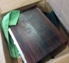
Ah, found the photos from the FedEX pickup... The case looks better, from the top, laying there than it really is - you could use it in a roll-top desk now... I'll upload a couple photos of the bashed-in front panel tomorrow when I have a few minutes.

I am optimistic though. Sheet metal can be straightened. I don't see any obvious damage to the boards, and I've a reasonable success rate at patching up old boards in worse shape than anything I see here with replacement point-to-point work.

Will
 

Attachments

  • IMG_0434.jpg
    IMG_0434.jpg
    82.5 KB · Views: 63
  • IMG_0438.jpg
    IMG_0438.jpg
    73.5 KB · Views: 59
Agree completely on the eBay policies thing - it's downright scary to sell these days, since it's /so/ easy for a buyer to completely screw a seller.

When I find a delicate item of interest on fleabay I contact the seller to make sure they are willing to coordinate packing with me, even if it may cost me a few $$$s more. Most have agreed, and I just don't bother to bid on the rest. And I take lots of pics on arrival & during unpacking.

I am surprised that the carrier was willing to deliver that tissue box in that condition. He should have taped a claim form to it.
 
Yup. Pillowcases. Two of them. In a toilet-paper shipping box. Toilet-tissue boxes have a crush-test rating of like 3 pounds or so - what they normally contain _is_ padding...

I was just thinking this, as since when did toilet paper come boxed? I have never in my life seen boxed toilet paper.. It mainly comes in some kind of thick-gauge cello wrap, no?
I'll upload a couple photos of the bashed-in front panel tomorrow when I have a few minutes.
Will

I'm in to see pics of the damage.

anytime i have to open my G-6700 and remove it from the shelf, I cannot imagine how much Sansui and other manufactures from the day just had to pay in shipping their units out here. Margins must have increased significantly just moving to plastic....
 
Last edited:
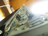
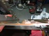
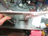
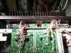
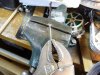
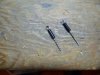
It was difficult to get photos that actually show what the damage to the chassis looks like, but here's what I've got (and one of the output transistors).

Pay attention to the direction(s) that the shafts and button stems are pointing - that's not an optical delusion. Also to how the glass "fits" the front panel. The glass is still flat.
 

Attachments

  • IMG_5427.jpg
    IMG_5427.jpg
    43.3 KB · Views: 52
  • IMG_5432.jpg
    IMG_5432.jpg
    53.9 KB · Views: 52
  • IMG_5433.jpg
    IMG_5433.jpg
    63.9 KB · Views: 49
  • IMG_5434.jpg
    IMG_5434.jpg
    109 KB · Views: 56
It was difficult to get photos that actually show what the damage to the chassis looks like, but here's what I've got (and one of the output transistors).

Pay attention to the direction(s) that the shafts and button stems are pointing - that's not an optical delusion. Also to how the glass "fits" the front panel. The glass is still flat.

Not as 'demolished' as I had imagined, but definitely not AOK. I would be reluctant to attempt to straighten the front panel or the heat sink. It won't affect the sounds, but either could break. I am surprised that the glass is still in one piece.

Looks like it has the original Sanken OP TRs. Your F-3058 bd looks different than mine and I would appreciate some pics (front & back) if you have to remove them to replace any of the OP TRs.

You should consider replacing all 8 of the OP TRs if any of them are bad. Definitely all 4 in the same channel. Consensus is that the circuitry on the driver end of the F-2980 is "touchy", and matching the components will help you get it playing again. I don't know how critical it is to match the gain, or how close the match should be. Maybe someone else can chime in here.
 
Not as 'demolished' as I had imagined, but definitely not AOK. I would be reluctant to attempt to straighten the front panel or the heat sink. It won't affect the sounds, but either could break. I am surprised that the glass is still in one piece.

It looks a lot worse in person. The extent to which the chassis is smushed in around the tone-control area is really not obvious from the photos. I'm really surprised the glass is still intact as well. I'd guess the knobs, and from them, the bottom of the chassis, took the worst of it.

I'm pretty sure I can reflatten the front panel, but the heat sink is stressed enough that I'm pretty sure it'll break if bent back. I can always cut a new front panel out of plate if I get desperate.

Looks like it has the original Sanken OP TRs. Your F-3058 bd looks different than mine and I would appreciate some pics (front & back) if you have to remove them to replace any of the OP TRs.

Will do. They're definitely different boards than any I've seen well-documented online, and different from the schematic.

Only single .33Ohm emitter resistors on them, rather than paired as per the manual.

You should consider replacing all 8 of the OP TRs if any of them are bad. Definitely all 4 in the same channel. Consensus is that the circuitry on the driver end of the F-2980 is "touchy", and matching the components will help you get it playing again. I don't know how critical it is to match the gain, or how close the match should be. Maybe someone else can chime in here.

I'm currently hoping to get it back in decent running shape with the original semiconductors in place, but, if I have to replace transistors I'll probably do a clean sweep from end to end and put in matched pairs as much as I can. I'd rather it either be "original", or new, rather than some hybrid hodgepodge.
 
Not as 'demolished' as I had imagined, but definitely not AOK. I would be reluctant to attempt to straighten the front panel or the heat sink. It won't affect the sounds, but either could break. I am surprised that the glass is still in one piece.

Looks like it has the original Sanken OP TRs. Your F-3058 bd looks different than mine and I would appreciate some pics (front & back) if you have to remove them to replace any of the OP TRs.

You should consider replacing all 8 of the OP TRs if any of them are bad. Definitely all 4 in the same channel. Consensus is that the circuitry on the driver end of the F-2980 is "touchy", and matching the components will help you get it playing again. I don't know how critical it is to match the gain, or how close the match should be. Maybe someone else can chime in here.

That is a late model, it has the extruded heatsink rather than the cast heatsink.

It also has the MT200 output transistors, there are only 2 per channel.

It has a revised F2809 board, quite different from the early ones.

The digital supply board is also different.

You can get substitutes for the MT200 devices, not a problem.

You don't see these very often, the one I sold to my friend is the same as this.
 
It looks a lot worse in person. The extent to which the chassis is smushed in around the tone-control area is really not obvious from the photos. I'm really surprised the glass is still intact as well. I'd guess the knobs, and from them, the bottom of the chassis, took the worst of it.
The glass is not glass, its an acrylic plastic, that will be why its still in one piece.

I'm pretty sure I can reflatten the front panel, but the heat sink is stressed enough that I'm pretty sure it'll break if bent back. I can always cut a new front panel out of plate if I get desperate.

Because the heat sink is extruded, you actually might be able to straighten it, if it was the cast version you'd be in trouble though.


Will do. They're definitely different boards than any I've seen well-documented online, and different from the schematic.

Yep, as stated, this is the last revision of the G7700, not many around, but fortunately, they dont seem to be as temperamental as the earlier ones.

Only single .33Ohm emitter resistors on them, rather than paired as per the manual.

Yep, because there are only two output transistors per channel, those emitter resistors should be 7watt too, larger than the earlier models.
When the output transistors fail in these they often take out the emitter resistors too.

Do NOT use the manual for this amp because the output section is quite different from what is published in the manual.


I'm currently hoping to get it back in decent running shape with the original semiconductors in place, but, if I have to replace transistors I'll probably do a clean sweep from end to end and put in matched pairs as much as I can. I'd rather it either be "original", or new, rather than some hybrid hodgepodge.

No need to match transistors, thats what the Bias and DC offset adjustments are for....
Close enough is good enough, catch it on the adjustment.
 
They named the models appropriately "G" for "Geez" then add your own ending, like "Geez they eat a lot of o/p bjt's" :-) I have given up on them!!
All I can add is cheap, cheap, cheap using one pair of o/p's.
 
Because the heat sink is extruded, you actually might be able to straighten it, if it was the cast version you'd be in trouble though.

The bend in the heat sink fin is pretty significant, even for extruded. It might not break, but the thermal properties across the previously bent region would be severely compromised. Not a significant problem either way though, it's not like there's a bunch of surface-area involved.

Do NOT use the manual for this amp because the output section is quite different from what is published in the manual.

I didn't have much time this weekend to talk to it (My non-freezing daylight hours get eaten on a new building project), but I did stare at the far end of the F-2980 board and its connection to the F-3058 boards, and it looks like the testpoints for the bias adjustment are the same - leastwise the emitter resistors trace back to the same points on the F-2980 as far I can see.

Does measuring bias there remain a safe assumption? And the same pots for bias and offset?

Any objections to bringing a test point loop up to the top of the board from that annoying empty 87/88 hole?

Recommendations on a good bias setting for these OP transistors?


No need to match transistors, thats what the Bias and DC offset adjustments are for....
Close enough is good enough, catch it on the adjustment.

Aww - where's the fun in that?
 
The bend in the heat sink fin is pretty significant, even for extruded. It might not break, but the thermal properties across the previously bent region would be severely compromised. Not a significant problem either way though, it's not like there's a bunch of surface-area involved.

Bend it back, don't bend it back, doubt it will make any difference.....


I didn't have much time this weekend to talk to it (My non-freezing daylight hours get eaten on a new building project), but I did stare at the far end of the F-2980 board and its connection to the F-3058 boards, and it looks like the testpoints for the bias adjustment are the same - leastwise the emitter resistors trace back to the same points on the F-2980 as far I can see.

Some of it is the same, some not, you just can't rely on it...

Does measuring bias there remain a safe assumption? And the same pots for bias and offset?

Bias test points are the same...

Any objections to bringing a test point loop up to the top of the board from that annoying empty 87/88 hole?

Up to you, anything to make something easier is a good thing.

Recommendations on a good bias setting for these OP transistors?

Can't remember, I measured on my scope back at on of the class A drivers until the crossover distortion disappeared....

Its somewhere between 5-10mV from memory....

Aww - where's the fun in that?

If you find it fun to match the transistors, no harm in it, but I'd rather get the thing running and out the door if you know what I mean...
 
re: Bias on this version:

Can't remember, I measured on my scope back at on of the class A drivers until the crossover distortion disappeared....

Its somewhere between 5-10mV from memory....

Works for me. Do you consider visual absence of the crossover distortion to be an adequate adjustment, or do I do something like invert and sum the output with the input, and try to minimize the result?

Keep in mind, physicist here, I'm long on theory, and I know to run a fair bit of instrumentation, but I'm terribly limited when it comes to audio applications.

If you find it fun to match the transistors, no harm in it, but I'd rather get the thing running and out the door if you know what I mean...

Ah, if I was trying to fix the thing for any practical purpose, that'd be my route as well, but the only reason for screwing with this thing is because some ass tried to destroy it, and it satisfies my sense of irony to make it unnecessarily right again.
 
This set of pics shows how I made & installed a set of standoff test points to get around the problem of accessing "that annoying empty 87/88 hole". I don't understand why Sansui didn't put a clip in them like they did for A & B.

P1030583.JPG P1030585.JPG P1030587.JPG
 
Last edited:
This set of pics shows how I made & installed a set of standoff test points to get around the problem of accessing "that annoying empty 87/88 hole". I don't understand why Sansui didn't put a clip in them like they did for A & B.

http://s1110.photobucket.com/user/ghazzer/library/Pics for AK/Standoff Test Point?sort=2&page=1

That's quite nice. What's the plastic tubing called that you ran that through? I've seen it used in many things, but never knew what to search for to buy a pile.
 
What's the plastic tubing called that you ran that through?

It is a short piece of insulation pulled off of a piece of 14g 'house' wire. I wanted something stiffer than heat shrink. You can easily buy a pile of it at Walmart or your local H/W store.
 
How impolite of me to start lurking on my favorite series of 'G' to assist with and not say welcome to AK :D
-Lee
 
It is a short piece of insulation pulled off of a piece of 14g 'house' wire. I wanted something stiffer than heat shrink. You can easily buy a pile of it at Walmart or your local H/W store.


Now that is downright clever. I go through a relative ton of 12 and 14g, and it seems like there's always bits of insulation drifting around on the floor.
 
So, the weather cooperated, if you want to call it that, and I had time to work on the 7700 today.

First the good news:

Put in new 25-turn bias and offset pots.

For the record, the old pots were all pretty much in the middle of the range - 45-55 ohms on each of them after I got them out.

Got the offset into the 0mv range, but it's bouncing back and forth between around -7mv and +7mv on both channels now.

Injected a tone and spent a bunch of time chasing it around, and finally figured out why one channel was dramatically lower than the other: it was a couple broken traces on the tone board. Patched around them point-to-point, and we've got balanced signal on both channels now - woohoo!

Added a couple extra test points to the far end of the output boards, so now I can measure bias across either of the emitter resistors.

And then we get to the confusing news:

I've got bubkus for bias... Even if I give it close to 100 ohms on the bias pots, I only get about 1.7mV across the emitter resistors. Way better than having blown something up, but, now I've got to figure out why I can't bring the bias current up.

As an aside - it's not something I changed - I couldn't read anything on the bias test points before switching out the bias pots either.

I did a real quick A/B comparison between measured resistor values and voltages around the 2980 board, and I didn't notice anything wildly different between the channels, but, both sides have got nothing for bias, so maybe the same component on both sides has gone off. Need to find my glasses so that I can read the resistors and board to see what might not match up.

Anyone have any suggestions on where to look first?
 
Last edited:
Is there any place in the bias loop(s) where the measured voltage varies as you adjust the trimmer(s)?

It is difficult to imagine a common point between the channels that could be pulling the bias circuits down. Measuring a voltage drop ACROSS the emitter resistor indicates that there is a current flowing in the loop.
 
Back
Top Bottom