Catfish Phil
New Member
New here and amateur at repairing electronics - started by dissecting radios and TV's as a kid in 1972 or so, even tapped the phono inputs of our family's GE phonograph to work as a guitar amp - Mom was mad at me!
This lovely, clean G-9000 was obtained from the original owner about ten years ago and have finally gotten serious about getting it functional and in regular use.
This forum is fantastic! I've searched and read every G-9000 (and similar model) thread I could find on the subject of restoring dropped channels and just cleaning and general maintenance as well. My girlfriend has an audio generator and oscilloscope on her deceased husband's workbench and I would be willing to learn how to use test equipment to get this repaired.
The unit is clean as a whistle - the problem started out before I got it with an existing scratchy volume control and other pots and switches. Disassembled and sprayed out everything when I first got the unit, and that helped, but it was not enough.
Second time I sprayed out everything, about two or three years ago, the ribbon cable from F-2805 Mic. Amp Circuit Board had become disconnected where it is soldered to F-2795 Mic. Amp. Circuit Board.
This is a photo of the damage to the pcb traces and a photo of the schematics.
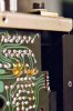
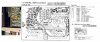
Would not having the Mic Jack Circuit Board properly connected to the Mic Amp Circuit Board cause the right channel to drop out?
Can I simply remove the ribbon cable from F-2795 and perhaps solder in a jumper so the amp card sees "no mic in mic jack?" (If this could possibly be causing the right channel to drop - I cannot figure this out for myself by reading the schematic).
Or, should I repair the traces and keep the mic feature functional? I am never going to plug a damned microphone into this unit. Perhaps Sansui should have utilized a ribbon jack/plug here to prevent this - I was careful as could be and the damage still happened. Saw a mention in another thread about this same unfortunate thing happening. Bending the ribbon stressed the edge of the board, widened the solder holes, etc. The copper traces leading up to the ribbon cable are broken away from the board .
I am convinced something in the preamp is causing loss of right channel signal going to the amp.
Every toggle switch, button, rotary switch and pot has been triple cleaned with DeOxit, worked and worked, and there are no wonky switches or cutting out of audio on the left channel, which sounds great. Before the latest cleaning last night, there was just a little cross talk in my headphones from the left channel to the right, and that has disappeared. The "connect" switch, power switch and headphone jack are all clean.
Audio through a mixing board was run directly through the amp to good speakers and all amp channels are great - A left and right, B left and right - the amp output is nice and clean, loud and lovely. The protection circuit and A/B relays are good - tapping on them changes nothing.
G-9000 radio audio was pulled from the G-9000 pre-amp outputs to a different, working amp/speakers - FM and AM function are great, but there's no audio from the right channel - good, scratch-free audio does come from the lleft channel. Connected a turntable - no right channel but again left is fine. So, I'm convinced it's clearly a preamp issue.
I've spent five days going through the unit, inspecting solder joints, cleaning plugs, examining pc boards for leaking capacitors or heat damage from resistors - not seeing anything out of the ordinary other than the damaged pcb.
Check out how the ribbon cable damaged the traces - on the right side of the F-2975 board. Simply resoldering is not going to fix it.
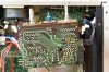
Could it be the mic ribbon cable damage, or is this inconsequential and I need to continue looking elsewhere?
Thank you for your help!!
(ETA: clarity about the traces being broken away, relocating the photos)
This lovely, clean G-9000 was obtained from the original owner about ten years ago and have finally gotten serious about getting it functional and in regular use.
This forum is fantastic! I've searched and read every G-9000 (and similar model) thread I could find on the subject of restoring dropped channels and just cleaning and general maintenance as well. My girlfriend has an audio generator and oscilloscope on her deceased husband's workbench and I would be willing to learn how to use test equipment to get this repaired.
The unit is clean as a whistle - the problem started out before I got it with an existing scratchy volume control and other pots and switches. Disassembled and sprayed out everything when I first got the unit, and that helped, but it was not enough.
Second time I sprayed out everything, about two or three years ago, the ribbon cable from F-2805 Mic. Amp Circuit Board had become disconnected where it is soldered to F-2795 Mic. Amp. Circuit Board.
This is a photo of the damage to the pcb traces and a photo of the schematics.
Would not having the Mic Jack Circuit Board properly connected to the Mic Amp Circuit Board cause the right channel to drop out?
Can I simply remove the ribbon cable from F-2795 and perhaps solder in a jumper so the amp card sees "no mic in mic jack?" (If this could possibly be causing the right channel to drop - I cannot figure this out for myself by reading the schematic).
Or, should I repair the traces and keep the mic feature functional? I am never going to plug a damned microphone into this unit. Perhaps Sansui should have utilized a ribbon jack/plug here to prevent this - I was careful as could be and the damage still happened. Saw a mention in another thread about this same unfortunate thing happening. Bending the ribbon stressed the edge of the board, widened the solder holes, etc. The copper traces leading up to the ribbon cable are broken away from the board .
I am convinced something in the preamp is causing loss of right channel signal going to the amp.
Every toggle switch, button, rotary switch and pot has been triple cleaned with DeOxit, worked and worked, and there are no wonky switches or cutting out of audio on the left channel, which sounds great. Before the latest cleaning last night, there was just a little cross talk in my headphones from the left channel to the right, and that has disappeared. The "connect" switch, power switch and headphone jack are all clean.
Audio through a mixing board was run directly through the amp to good speakers and all amp channels are great - A left and right, B left and right - the amp output is nice and clean, loud and lovely. The protection circuit and A/B relays are good - tapping on them changes nothing.
G-9000 radio audio was pulled from the G-9000 pre-amp outputs to a different, working amp/speakers - FM and AM function are great, but there's no audio from the right channel - good, scratch-free audio does come from the lleft channel. Connected a turntable - no right channel but again left is fine. So, I'm convinced it's clearly a preamp issue.
I've spent five days going through the unit, inspecting solder joints, cleaning plugs, examining pc boards for leaking capacitors or heat damage from resistors - not seeing anything out of the ordinary other than the damaged pcb.
Check out how the ribbon cable damaged the traces - on the right side of the F-2975 board. Simply resoldering is not going to fix it.
Could it be the mic ribbon cable damage, or is this inconsequential and I need to continue looking elsewhere?
Thank you for your help!!
(ETA: clarity about the traces being broken away, relocating the photos)
Last edited: