• The move to the new server is done. There are some software and database maintenance updates in process. This has us passing the hat around to help out. We appreciate any donations. Seriously, even a dollar helps. The payment page may be found here - https://www.audiokarma.org/support.html

G-9000DB Distorted sound on left channel (Solved)

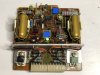
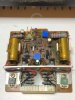
While i'm waiting for parts to arrive from Mouser, I have a question. The diagram of the driver board shows 4 resistors in each area I marked in red, but the board itself has 5.
The board itself has no info as well under one of the resistors. Any idea what I'm missing here?
 

Attachments

  • F-2806.jpg
    F-2806.jpg
    107 KB · Views: 31
  • Resistors.jpg
    Resistors.jpg
    60.9 KB · Views: 21
While i'm waiting for parts to arrive from Mouser, I have a question. The diagram of the driver board shows 4 resistors in each area I marked in red, but the board itself has 5.
The board itself has no info as well under one of the resistors. Any idea what I'm missing here?
That 5th resistor is either a previous repair someone did trying to fix an issue or a service bulletin update that was done, or it's supposed to be there depending on whether you have a manual that is for a later or earlier unit than yours. Originally there would be a jumper there, not a resistor, according to the service manual page, but this would depend if the serial number of your unit is covered by the particular "revision" of service manual you have for it. The board may in fact be correct for the circuit and the schematic is wrong, or could be the other way around.

I found this exact issue with a KLH Model Twenty-Seven receiver I am restoring. But it gets better still.....the manual shows one thing, but what is actually there is different from the manual on one channel only! Turns out it has the revised board in one channel, and the original circuit design on the other channel. Since I was rebuilding both boards, I rebuilt the earlier board to the later specs and it works fine.
 
That 5th resistor is either a previous repair someone did trying to fix an issue or a service bulletin update that was done, or it's supposed to be there depending on whether you have a manual that is for a later or earlier unit than yours. Originally there would be a jumper there, not a resistor, according to the service manual page, but this would depend if the serial number of your unit is covered by the particular "revision" of service manual you have for it. The board may in fact be correct for the circuit and the schematic is wrong, or could be the other way around.

I found this exact issue with a KLH Model Twenty-Seven receiver I am restoring. But it gets better still.....the manual shows one thing, but what is actually there is different from the manual on one channel only! Turns out it has the revised board in one channel, and the original circuit design on the other channel. Since I was rebuilding both boards, I rebuilt the earlier board to the later specs and it works fine.
That makes so much sense now! I'll just order the "missing" one per the color code on the Resistor. Thank you! :)
 
Success!
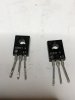
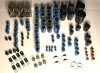
So Paul was right, replacing both Zeners on the Driver Board (though one was bad) did not fix the issue. Bias was fluctuating and sound distorted on the left channel. So I went ahead and replaced the 4 pre drivers with Echo’s recommended Fairchild Transistors. BAM!!! Issue solved. It’s been running for an hour with no issue and Bias+DC voltage are perfect at 16.2 and 0.0. Interesting, the original transistors were already set as ECB. I could easily tell that these were the originals per the soldering and comparing with the right driver board. Pictures show the two bad drivers and total stuff replaced. Next I’ll replace the same parts on the other board. The speaker pots are bad too so I’ll look at dismantling and putting something else. Any recommendations from this amazing group are welcome.

Thank you Paul and all for staying with me
 

Attachments

  • 8BB11A43-4B5C-466D-8519-33D084164788.jpeg
    8BB11A43-4B5C-466D-8519-33D084164788.jpeg
    26.3 KB · Views: 49
  • Parts replaced.jpg
    Parts replaced.jpg
    105.2 KB · Views: 36
Last edited:
Well, I have only worked on what seems like 100 of these darn things.... :) Really though, they are quite special. Glad you got it running. I will let you figure out the rest. ;) (Hint: Use the search function to find other peoples ideas for replacing the speaker jacks with binding posts)
 
Last edited:
Sorry, I missed that you hadn't replaced the drivers. Those uniwatt transistors get flakey. They are the ones that look like this:
t_6440.jpg
 
Sorry, I missed that you hadn't replaced the drivers. Those uniwatt transistors get flakey. They are the ones that look like this:
t_6440.jpg
Thanks Warren!
You mean the 4 transistors on the Driver Boards (F-2806)? TR05,08 2SA818 which I replaced with: KSA1381 and TR06,07 2SC1628 which I replaced with: KSC3503.
Or do you mean TR09 and TR10 (Black and Green) (2sc2238, 2sa968lb) if so, would MJE15032, MJE15033 be a good replacement?
While I'm at it, any other transistors you recommend I change anywhere? the 9000 is still open :)
 
Thanks Warren!
You mean the 4 transistors on the Driver Boards (F-2806)? TR05,08 2SA818 which I replaced with: KSA1381 and TR06,07 2SC1628 which I replaced with: KSC3503.
Or do you mean TR09 and TR10 (Black and Green) (2sc2238, 2sa968lb) if so, would MJE15032, MJE15033 be a good replacement?
While I'm at it, any other transistors you recommend I change anywhere? the 9000 is still open :)
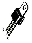
They are 2SA818 and 2SC1628. See the funky metal tab that comes out the middle of the top instead of being even with the back, like a TO-220? This was called a Uniwatt case because the transistors were supposed to be good for 1 Watt power dissipation. I don't think the Motorola transistors that were like this go bad, but the Japanese transistors that look like this are crap. Do not replace with MJ15032 and MJ15033, the gain is not high enough. KSA1381 and KSC3503 are what you want to use.
 
Last edited:
They are 2SA818 and 2SC1628. See the funky metal tab that comes out the middle of the top instead of being even with the back, like a TO-220? This was called a Uniwatt case because the transistors were supposed to be good for 1 Watt power dissipation. I don't think the Motorola transistors that were like this go bad, but the Japanese transistors that look like this are crap. Do not replace with MJ15032 and MJ15033, the gain is not high enough. KSA1381 and KSC3503 are what you want to use.
Thanks Warren. You did manage to confuse me :idea:
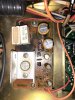
I replaced everything I marked in color. The Red ones are the Pre Drivers I replaced. this is what eventually solved my issue.
We are probably talking about the same ones, but just making sure:
1. I replaced both 2SA818 with Fairchild KSA1381
2. I replaced both 2SC1628 with Fairchild KSC3503

My Question is, do I also want to replace TR09 and TR10 (Black and Green) (2sc2238, 2sa968lb), or are they not privy to fail? Just trying to be proactive :)

IMG_0931.jpg IMG_0911.jpg IMG_0924.jpg

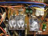
Also used the time to replace the caps on the Tuner power supply (F-2810) & found 1 bad one. Also both speaker relays.
 
Last edited:
"My Question is, do I also want to replace TR09 and TR10 (Black and Green) (2sc2238, 2sa968lb), or are they not privy to fail?"

No, do not under any circumstances change those transistors if they are working, they have a much higher transition frequency than any replacement you are likely to find in a TO220. They are 100mhz, most replacements are around 30mhz.
They do not tend to fail as a rule, I would leave them.
 
"My Question is, do I also want to replace TR09 and TR10 (Black and Green) (2sc2238, 2sa968lb), or are they not privy to fail?"

No, do not under any circumstances change those transistors if they are working, they have a much higher transition frequency than any replacement you are likely to find in a TO220. They are 100mhz, most replacements are around 30mhz.
They do not tend to fail as a rule, I would leave them.
Works for me, thank you Kevin :)
 
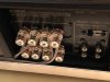
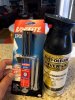
Finally finished the project and I'm so proud. I also replaced the old and broken speaker terminals by using two glued together plexiglass boards, some paint and new posts.
The Marantz 2275 is waiting on the bench for an overhaul, but that's for a different post and board :)
Completed project.jpg Speaker posts.jpg Speaker posts prep1.jpg Speaker Posts prep2.jpg Speaker posts prep3.jpg
 
Last edited:
How long is the protect cycle at power up? Nice job btw.... Looks very very nice :) You got off pretty good here, and AK accepts donations. Subscribe dude. Just sayin ;)
 
Last edited:
How long is the protect cycle at power up? Nice job btw.... Looks very very nice :) You got off pretty good here, and AK accepts donations. Subscribe dude. Just sayin ;)
Thank you Paul! The protect takes about 8-9 seconds. I tested after it has been working for about 3 hours playing music. I think that after being off the whole night it took 4-5 seconds but I'll have to test it again.
 
Back
Top Bottom