

You are using an out of date browser. It may not display this or other websites correctly.
You should upgrade or use an alternative browser.
You should upgrade or use an alternative browser.
Getting Bass from TD15M in a 5.5 ft³ Cabinet
- Thread starter dumptruck
- Start date


Here is a bit of data from my set, for comparison's sake.
Just to have the info here for newcomers, I have the AE Lambda TD15M 8ohm in internal golden ratio cabinets of 5cu.f, with a bottom slot-vent totaling 190sq.cm in area, tuning the cabinet to ~32Hz.
I measured the following with the cab on its head, thus the vent was up in the air. Mic was placed mid-cone, ~1cm away, and very close to the baffle plane for the vent measurement. Vent output was adjusted by -13dB, as per 20*log(190/855).
Blue trace = woofer, near-cone
Red trace = near-vent, -13dB adjustment
Green trace = summed response

This is fairly close to simulation, with a f10 point in the mid-30ies. It sounds good in my small room.
Disregarding the fact that DT's woofer is 4ohm, the major differences are the cabinet shapes and tuning frequencies, his more squat/stout and mine taller/leaner, which I'm hoping helps give a bit of punch around 90-100Hz, as it verges on an MLTL, can't really prove this though.His Fb is mid-40ies while mine is low-30ies. I would expect this to give stronger output from 40-60Hz versus my cab, which trades this for some reach sub-40Hz.
az
That looks good AZ. I assume you can bring up the lower end a bit with placement. That is certainly in keeping with what I've seen out of the Ms.

audiozaz
rtfm!? - tl;dr
That looks good AZ. I assume you can bring up the lower end a bit with placement. That is certainly in keeping with what I've seen out of the Ms.
Yes and no. No as in my room is small and I don't have much leeway towards placement, but I tailored the bass response with such a low tuning so that it works in this very situation. I could essentially make it flat to 35Hz with the miniDSP if I wanted. I used to have speakers flat down to 35-40Hz and it was a bit much with room modes.
az
audiozaz
rtfm!? - tl;dr
One thing I like about the TDs is the low Le. A high Le will smooth out the signal just like the choke in an amp. A low Le lets the signal come through untouched. Much better bass and mid clarity.
The 1501FE is a great driver too.
The low inductance would also make Xover work much easier and simpler with no need for a zobel.
az
AZ, your measurements seem to make sense. Can you remind me how your port length compared to simulation? I'm running break in signal on the second woofer for a while at the moment. I'm going to try to measure parameters later. I'm not even sure what I'm trying pin down here  . I guess I want to see if I get correlation with the impedance plot when I measure parameters, I may investigate the 50Hz blip, I'm still suspicious that my port output is summing poorly and may see what I can try for other port locations or something.
RE: the TD15M and "issues":
The only clear failing on the part of the driver in my measurement above, as far as I can tell at least, is compromised performance above ~900Hz (indicated by the impedance). This is surprising to a lot of people expecting them to be great to 4kHz, but it's not really a big deal. This is discussed a little in my ewave thread and extensively on diyaudio.
The possible strange bass stuff this thread is about is just normal for an amateur holding their BR attempts to as bright a light as possible, I'd say.
. I guess I want to see if I get correlation with the impedance plot when I measure parameters, I may investigate the 50Hz blip, I'm still suspicious that my port output is summing poorly and may see what I can try for other port locations or something. RE: the TD15M and "issues":
The only clear failing on the part of the driver in my measurement above, as far as I can tell at least, is compromised performance above ~900Hz (indicated by the impedance). This is surprising to a lot of people expecting them to be great to 4kHz, but it's not really a big deal. This is discussed a little in my ewave thread and extensively on diyaudio.
The possible strange bass stuff this thread is about is just normal for an amateur holding their BR attempts to as bright a light as possible, I'd say.
Last edited:
audiozaz
rtfm!? - tl;dr
AZ, your measurements seem to make sense. Can you remind me how your port length compared to simulation?
My vent is 3 rectangular sections totaling 190cm^2, 26cm long. In WinISD, a round vent of equivalent CSA and same length nails it at 32Hz for 5cu.f. If I set it for 3 rectangular vents, it yields 35Hz.
Well, if we look at my above graphs, Fb is really more like 30Hz, if we go with the cone dip. I though I remembered measuring 32Hz.
I'm not set up to do impedance sweeps, other than manually, which is very laborious. I tried to set up a jig with HolmImpulse and a resistor once, but was getting some I/O weirdness from my UCA-222 USB interface, even though it is supposed to be full duplex.
az
Last edited:
Did you try the type of jig that uses amplifier output? That's what I ended up using, because trying to use the output of my USB interface I got high noise and some sort of instability that would cause it to freak out and turn off. I don't use diode protection or anything, but that's because the interface only cost me $40 (used Lexicon Lambda), and I want to replace it with a 192kHz unit anyway.
audiozaz
rtfm!? - tl;dr
Did you try the type of jig that uses amplifier output? That's what I ended up using, because trying to use the output of my USB interface I got high noise and some sort of instability that would cause it to freak out and turn off. I don't use diode protection or anything, but that's because the interface only cost me $40 (used Lexicon Lambda), and I want to replace it with a 192kHz unit anyway.
Output was from the amp, but I wanted to use the interface's inputs to read the voltage across a series resistor, much like I do manually. I would have to make an Excel spreadsheet to quickly convert the decibels from Holm into voltages and apply the proper calculations for impedance.
az
audiozaz
rtfm!? - tl;dr
P.S. My last measurement shows approx. 5dB higher bass response than AZ's even down at 30Hz (~-15dB vs ~-10dB). Both of our measurements are probably suspect in the bottom octave, though.
FWIW you might be using a better mic than me. I have a Samson Go Mic USB mic. Response in Omni-mode shows flat behavior in the bass though. I was getting some weirdness at first, but it was switched to cardioid and was likely getting some proximity effect, reading too much bass. I then measured omni.
I hope I did things right, using RayW's technique. 20*log(port_CSA/driver_Sd) yielded -13dB adjustment, which I did before summing responses.
az
I'm using the EMM-6 with calibration. If you want to try to get the auto impedance thing working, maybe try a pot on each input wire to the USB thing? Maybe Holm works like this too, but if you use LIMP, you can set the signal in action on the config screen and see the levels. I do this and use the input level pots on my USB interface to adjust until the high input is low enough to have some headroom. Then, I connect a resistive load and start the measurement going, adjusting the low input pot to "calibrate" until the readout is correct.

I hope I did things right, using RayW's technique.
That wasn't me. I learned it a looooong time ago. It was in Joe D'appolito's book on measuring speakers but I think I was introduced to the method before that.
DT, just for fun would it be possible to reverse the phase of your adjusted port measurement in the software before you add it to the woofer measurement?
audiozaz
rtfm!? - tl;dr
That wasn't me. I learned it a looooong time ago. It was in Joe D'appolito's book on measuring speakers but I think I was introduced to the method before that.
DT, just for fun would it be possible to reverse the phase of your adjusted port measurement in the software before you add it to the woofer measurement?
Then thanks for relaying it here.
I would not have thought of adjusting for equivalent radiating area, but I suppose it makes some sense since it give results close to simulation.I tried inverting the phase for fun, it only produced a notch at Fb, somewhat less output above Fb and more output below.
az
Yep, can do See gray line below.just for fun would it be possible to reverse the phase of your adjusted port measurement in the software before you add it to the woofer measurement?
If I don't do the -10.6dB adjustment on the port, I get this rather tidy summing with the reverse phase. I'm having a little trouble seeing why that happens, as it looks like there should be a perfect null around 38Hz in the reversed version.. :headscrat:
Attachments
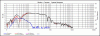

Yep, can do See gray line below.

That's closer to what I would expect with your box. It looks to be -6dB (eyeballing average output at around 85dB on this graph) at about 45Hz where the sims said ~40. The overall shape relates well to zaz's, only with a higher tuning.
On the red line, the dip is supposed to be there. It's the port tuning frequency, where the woofer output is minimum and the port output is maximum. When measuring the woofer nearfield, the port output is not there (it's off the chart low compared to the woofer), so you see the woofer minimum. If you go all the way back to the first page, you can see the response with the ports plugged, which has no dip.
Now, the dip in the merged response (black line) is a different matter, but it hinges on the phase of my measurements, which may or may not be trustworthy.
Now, the dip in the merged response (black line) is a different matter, but it hinges on the phase of my measurements, which may or may not be trustworthy.