• The move to the new server is done. There are some software and database maintenance updates in process. This has us passing the hat around to help out. We appreciate any donations. Seriously, even a dollar helps. The payment page may be found here - https://www.audiokarma.org/support.html

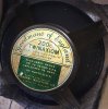
Goodmans speakers- help identify please

Nice detective work!

If you can insert a vacuum cleaner wand into the port that will remove internally produced dust during the sawing process which will otherwise accumulate on the cone and clog the voice coil. Difficult to remove once it gets into the drivers.

As long as you are cutting off the backs and installing cleats, you might consider chamfering the ports, likely not performed out of ignorance, and fully lining the cabinet, which was not done to save manufacturing expense.

Troels Gravesen has presented actual measurements for the benefits of chamfering:
 
Nice detective work!

If you can insert a vacuum cleaner wand into the port that will remove internally produced dust during the sawing process which will otherwise accumulate on the cone and clog the voice coil. Difficult to remove once it gets into the drivers.

As long as you are cutting off the backs and installing cleats, you might consider chamfering the ports, likely not performed out of ignorance, and fully lining the cabinet, which was not done to save manufacturing expense.

Troels Gravesen has presented actual measurements for the benefits of chamfering:
incredible thank you!
 
Nice work in removing the backs.

Some observations.

Crossover and Adding a Super-Tweeter

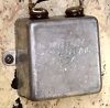
The tweeter uses a PIO capacitor as a first-order filter. The capacitor was never particularly good when new, and has degraded over the years to the point it may fail, which would destroy the tweeter by admitting lower-frequencies. The capacitor should be replaced with a modern polypropylene film capacitor, suitably bypassed (see my other writings on the subject), for both the sound and risk of damage to the tweeter.

The Twinaxiom clearly is being run full-range without any crossover. It might not be a bad idea to add an inductor wherever the tweeter cuts over, instead of relying on the driver to be mechanically limited. True, the whizzer cone does improve emission of higher frequencies, but it does so with (a) increasing distortion with increasing frequency, because of the driver's mechanical properties, likely also having ringing, and (b) comb effects because as the drivers are emitting in the same frequency band, but are not within 1/4 wavelength. If the crossover point is about 2,500 Hz to 3,000 Hz, an air-core inductor will not be very expensive.

It might not be a bad idea to add a soft-dome tweeter as a super-tweeter, cutting over at something like 8,000 Hz and running to 24,000 Hz, because cone tweeters do not properly reproduce above about 9 to 10,000 Hz. I don't know what the limit is for that Goodman's tweeter, but it will not be much above about 8,000 Hz before it begins to become spikey and irregular, and then die at about 10,000 Hz, rapidly falling off in SPL with increasing distortion.

Using two tweeters will preserve the driver blending between the full-range and the tweeter — both are comparable drivers from the same manufacturer, and expected to reasonably together work and have similar SPL in the operating range — but provide the higher-frequency response (aka "air") necessary for optimal sound. Goodmans cone tweeters, alas, are not very good when compared to modern drivers. I will be making the super-tweeter modification to my Goodmans speakers, because it is no longer the 1960s, and far, far better options exist. This is the same modification I created for the Bozaks, and the response has been positive because it preserves the inter-driver blending in the region where humans best hear.

An L-pad for the tweeter, and super-tweeter if added, would be beneficial to better tune the higher frequency response, as overlapping drivers may be a but shouty.

Chamfering

As I have above described, the baffle would benefit from chamfering of the drivers and port. It is possible to inexpensively purchase pre-made ports with smooth edges. I do not know which brands are currently good, just that they exist.

Port Tuning

Goodmans drivers tend to benefit from aperiodic loading — aka the "Acoustic Resistance Unit" or "ARU" — which is a fancy way of saying the port is tuned for the lower frequencies by covering it with ordinary filter scrim. (The white stuff used for aquarium and other filters.)

That is elsewhere documented on AK, and I've somewhere posted Ted Jordan's paper from the 1950s on the subject. I'll dig it out and post it if you are unable to locate it. Easily and inexpensively tried.

Other port tuning techniques use stuffing, but Goodmans were designed for layers of scrim and this is a simple addition. Try it on one speaker, play a mono signal and A/B switch between the speakers to see if you find sonic improvements in bass response.

Cabinet Lining

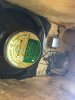
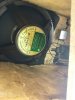
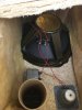
I cannot tell if that lining is fiberglass or Tufflex, a reprocessed cellulose. Looks like Tufflex, but could be a dense mat of fiberglass. Hard to say from the photos.

Could be fiberglass, though, as Goodmans was known to use this in its speakers. If Fiberglass, you might consider removing the entirety of the fiberglass (outdoors and with gloves and a mask) and replacing with cotton batting, fully lining the interior and covering the exterior of the port. The fiberglass was not chosen over cotton for superior sonics, but for lower cost. This is also why the lining is not complete for the baffle or present over the port. Just cost-savings measures. The emergence of fiberglass particles into your living environment via the port is not a good thing.

If Tufflex, covering the remaining bits of the baffle and port will reduce reflections. You may secure it to the port with twisted wire or cable ties. This will reduce reflections and improve the sound.

Nice score on the speaker!
 
Nice work in removing the backs.

Some observations.

Crossover and Adding a Super-Tweeter

The tweeter uses a PIO capacitor as a first-order filter. The capacitor was never particularly good when new, and has degraded over the years to the point it may fail, which would destroy the tweeter by admitting lower-frequencies. The capacitor should be replaced with a modern polypropylene film capacitor, suitably bypassed (see my other writings on the subject), for both the sound and risk of damage to the tweeter.

The Twinaxiom clearly is being run full-range without any crossover. It might not be a bad idea to add an inductor wherever the tweeter cuts over, instead of relying on the driver to be mechanically limited. True, the whizzer cone does improve emission of higher frequencies, but it does so with (a) increasing distortion with increasing frequency, because of the driver's mechanical properties, likely also having ringing, and (b) comb effects because as the drivers are emitting in the same frequency band, but are not within 1/4 wavelength. If the crossover point is about 2,500 Hz to 3,000 Hz, an air-core inductor will not be very expensive.

It might not be a bad idea to add a soft-dome tweeter as a super-tweeter, cutting over at something like 8,000 Hz and running to 24,000 Hz, because cone tweeters do not properly reproduce above about 9 to 10,000 Hz. I don't know what the limit is for that Goodman's tweeter, but it will not be much above about 8,000 Hz before it begins to become spikey and irregular, and then die at about 10,000 Hz, rapidly falling off in SPL with increasing distortion.

Using two tweeters will preserve the driver blending between the full-range and the tweeter — both are comparable drivers from the same manufacturer, and expected to reasonably together work and have similar SPL in the operating range — but provide the higher-frequency response (aka "air") necessary for optimal sound. Goodmans cone tweeters, alas, are not very good when compared to modern drivers. I will be making the super-tweeter modification to my Goodmans speakers, because it is no longer the 1960s, and far, far better options exist. This is the same modification I created for the Bozaks, and the response has been positive because it preserves the inter-driver blending in the region where humans best hear.

An L-pad for the tweeter, and super-tweeter if added, would be beneficial to better tune the higher frequency response, as overlapping drivers may be a but shouty.

Chamfering

As I have above described, the baffle would benefit from chamfering of the drivers and port. It is possible to inexpensively purchase pre-made ports with smooth edges. I do not know which brands are currently good, just that they exist.

Port Tuning

Goodmans drivers tend to benefit from aperiodic loading — aka the "Acoustic Resistance Unit" or "ARU" — which is a fancy way of saying the port is tuned for the lower frequencies by covering it with ordinary filter scrim. (The white stuff used for aquarium and other filters.)

That is elsewhere documented on AK, and I've somewhere posted Ted Jordan's paper from the 1950s on the subject. I'll dig it out and post it if you are unable to locate it. Easily and inexpensively tried.

Other port tuning techniques use stuffing, but Goodmans were designed for layers of scrim and this is a simple addition. Try it on one speaker, play a mono signal and A/B switch between the speakers to see if you find sonic improvements in bass response.

Cabinet Lining

I cannot tell if that lining is fiberglass or Tufflex, a reprocessed cellulose. Looks like Tufflex, but could be a dense mat of fiberglass. Hard to say from the photos.

Could be fiberglass, though, as Goodmans was known to use this in its speakers. If Fiberglass, you might consider removing the entirety of the fiberglass (outdoors and with gloves and a mask) and replacing with cotton batting, fully lining the interior and covering the exterior of the port. The fiberglass was not chosen over cotton for superior sonics, but for lower cost. This is also why the lining is not complete for the baffle or present over the port. Just cost-savings measures. The emergence of fiberglass particles into your living environment via the port is not a good thing.

If Tufflex, covering the remaining bits of the baffle and port will reduce reflections. You may secure it to the port with twisted wire or cable ties. This will reduce reflections and improve the sound.

Nice score on the speaker!

This is a wealth of information! Thank you for taking the time. I am reading through your detailed writeup and want to do justice to these speakers. When i initially auditioned, one speaker had a weak super tweeter but overall observation was they sounded really nice and thought they had some “serious potential”.

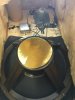
Before I begin searching for an appropriate inductor, x-over capacitor, and super-tweeter, etc Im going to sketch out the simple schematic and label to be on the same page. Did you notice the gold paper covering on the back of the full drivers? Like opening up an untouched treasure!

Also found this which may help ? 47EB4C81-98D3-4A0A-BCC5-7D55E471ED75.jpeg
 
Last edited:
Ok, some time to respond.

Much of this is from my thoughts and notes about modifying my own Goodmans units to clean up the crossovers which are poorly designed and always the weak point in the speakers.

Missing Crossover Filters (Beancounter Problem)

In the late 1960s and early 1970s market forces put great pressure on speaker manufacturers and corners, wherever possible, were cut to reduce costs. Many manufacturers cut corners, and Goodmans was not the only one. (HiFi hobbyists always malign accountants, but the fact is that management had to direct the engineers to hack up the crossovers and tell manufacturing what parts to purchase, so the fault really therein lies.)

The biggest savings came from running drivers full range, using only a first-order filter (capacitor) to control the low-end response and relying on the surround to mechanically limit the driver instead of adding inductors to the woofer and, if a three-way, the midrange. The effects will be deleterious on the sound:
Three-Way
Omitting the inductor for the woofer causes it to overlap with the midrange
Omitting an inductor for the midrange causes it to overlap with the tweeter

Two-Way
Omitting the inductor for the full-range (i.e. woofer/midrange) causes it to overlap with the tweeter.
​
Again, while beneficial for the bottom line, the sonics suffer. Most consumers could likely not hear the difference given the amplifier and source material (tape or LP) of the day and likely would not care.

For either configuration the resulting sound is muddier than with a full crossover. I have several Goodmans models which omitted the full crossover as a cost-savings measure, and also have a number of inexpensive speakers likely OEM'd by Coral which also omitted the inductors for the woofer and midrange.

The argument could be made that the fall-off in response of the whizzer cone was intentionally being boosted by a tweeter, but that's really not a good argument. The treble would be far too loud, since a full-range + tweeter configuration would be sufficient in treble and balanced, as would a woofer + midrange + tweeter. The tweeter, in face, often requires a little bit of attenuation. It's just a rolloff issue saving money at the expense of distortion.

Remedying the driver overlap will greatly clean up the sound.

Existing Crossover Point

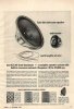
I do not have the datasheet for the Twinaxiom 200c (or Axiom 200c) driver, but I do have an ad which suggests pairing with a tweeter; see the attached file.

The Axiom 201 — as far as I know, the Twinaxiom 201 is the American version of the British Axiom 201 — is a 15 Ω driver which was the standard impedance for Goodmans drivers of that ilk.

15 Ω Driver

Assuming a 15 Ω driver, the capacitor value works out to:
Given:
C = 4 µF
R = 15 Ω

Then:

fc = 2,653 Hz ≈ 2,600 Hz​

I suspect the target goal was actually 2,500 Hz, but the 4 µF PIO capacitor was a stock value for motor-run capacitors and the unit was already in use by Goodmans for other lines and thus had benefits for simplifying stocking and volume discount. Consumer wouldn't care.

16 Ω Driver

If the speaker is 16 Ω, the numbers slightly downward shift:
Given:
C = 4 µF
R = 16 Ω

Then:

fc = 2,487 Hz ≈ 2,500 Hz​

Which is spot-on for 2,500 Hz.

Again, I suspect the motor-run capacitor was simply handy and inexpensive. The exact value for 2,500 Hz would be 4.24 µ which would have required a second capacitor to approximate. Life for crossover designers was simpler in those days.

Proposed Crossover Modification

Full-Range Inductor


What I would suggest, assuming you're willing to put a small money into the project, is add an inductor to better blend the full-range with the tweeter. That will remove some comb artifacts from multiple drivers operating in the same space without being within 1/4 wavelength and the distortion from higher frequencies in the cone.

You could keep the existing 2,650 point or downwards move it to 2,500. It really doesn't matter as long as both the capacitor and inductor match.

I suggest an air-core inductor which is not that expensive. To cross at 2,500 Hz at 15 Ω would be 0.95 mH. At 16 Ω it would be 1 mH. So not critical.

That would give you a smooth first-order blend between the full-range and the tweeter.

Inductor Value

For 2,500 Hz the inductor value would be 0.95 mH, fc = 2,516 Hz.

A 1 mH would be 2,387 Hz which requires a turn or so to be removed. Without access to an inductance meter this change is impossible.

Parts express has this for $10 to $26 depending upon gauge and construction:

So for $10 per speaker you will remove the overlap.

Capacitor

The PIO capacitor is degraded and muffling the tweeter, making it sound even worse than it would with overlap alone.

I therefore suggest adding a polypropylene capacitor suitable bypassed using 0.1 µF and 0.01 µF to improve high-frequency performance.

Crossing at 2,500 Hz would be 4.24 µF which can be built using either:
C = 4 µF + 0.15 µF + 0.01 µF
fc = 2,550 Hz

C = 4 µF + 0.15 µF + 0.1 µF + 0.01 µF
fc = 2,490 Hz​

Either one is close enough given the tolerances and fiction of nominal impedance. It's not critical.

Proposed Extension: Super-Tweeter

Paper-cone tweeters have poor high-frequency performance, and the Goodmans are no different. I'd keep that because it will match the characteristics of the full-range, but I would not expect the high-frequency performance to be good, and the tweeter will distort with higher frequencies. Just a fact of life with paper-cone tweeters.

If you like the sound, you might consider adding a super-tweeter as has been done for the Bozaks. My design crosses the Bozak tweeter, an aluminum cone design, at 8,000 Hz, which is high enough that the point is not taken in a region in which human hearing is highly acute, yet low enough that the distortion from the mechanical errors is minimized. A modern soft down then runs from 8,000 Hz to 24,000 Hz, limited to prevent ultrasonic oscillation from damaging the tweeter. You could try that, as the paper-cone should be fine at that frequency, operating without distortion.

The cost of adding (1) an inductor to the existing tweeter to form a band-pass and (2) constructing a high-frequency band-pass for the super-tweeter is small. Parts Express lists a 0.3 mH inductor for 8,000 Hz is $3, and the 0.1 mH for 24,000 Hz is $4:
The cost is basically stocking and putting it in a box.

The main cost here is the soft-dome tweeter.

 

Attachments

Ok, some time to respond.

Much of this is from my thoughts and notes about modifying my own Goodmans units to clean up the crossovers which are poorly designed and always the weak point in the speakers.

Missing Crossover Filters (Beancounter Problem)

In the late 1960s and early 1970s market forces put great pressure on speaker manufacturers and corners, wherever possible, were cut to reduce costs. Many manufacturers cut corners, and Goodmans was not the only one. (HiFi hobbyists always malign accountants, but the fact is that management had to direct the engineers to hack up the crossovers and tell manufacturing what parts to purchase, so the fault really therein lies.)

The biggest savings came from running drivers full range, using only a first-order filter (capacitor) to control the low-end response and relying on the surround to mechanically limit the driver instead of adding inductors to the woofer and, if a three-way, the midrange. The effects will be deleterious on the sound:
Three-Way
Omitting the inductor for the woofer causes it to overlap with the midrange
Omitting an inductor for the midrange causes it to overlap with the tweeter

Two-Way
Omitting the inductor for the full-range (i.e. woofer/midrange) causes it to overlap with the tweeter.
​
Again, while beneficial for the bottom line, the sonics suffer. Most consumers could likely not hear the difference given the amplifier and source material (tape or LP) of the day and likely would not care.

For either configuration the resulting sound is muddier than with a full crossover. I have several Goodmans models which omitted the full crossover as a cost-savings measure, and also have a number of inexpensive speakers likely OEM'd by Coral which also omitted the inductors for the woofer and midrange.

The argument could be made that the fall-off in response of the whizzer cone was intentionally being boosted by a tweeter, but that's really not a good argument. The treble would be far too loud, since a full-range + tweeter configuration would be sufficient in treble and balanced, as would a woofer + midrange + tweeter. The tweeter, in face, often requires a little bit of attenuation. It's just a rolloff issue saving money at the expense of distortion.

Remedying the driver overlap will greatly clean up the sound.

Existing Crossover Point

I do not have the datasheet for the Twinaxiom 200c (or Axiom 200c) driver, but I do have an ad which suggests pairing with a tweeter; see the attached file.

The Axiom 201 — as far as I know, the Twinaxiom 201 is the American version of the British Axiom 201 — is a 15 Ω driver which was the standard impedance for Goodmans drivers of that ilk.

15 Ω Driver

Assuming a 15 Ω driver, the capacitor value works out to:
Given:
C = 4 µF
R = 15 Ω

Then:

fc = 2,653 Hz ≈ 2,600 Hz​

I suspect the target goal was actually 2,500 Hz, but the 4 µF PIO capacitor was a stock value for motor-run capacitors and the unit was already in use by Goodmans for other lines and thus had benefits for simplifying stocking and volume discount. Consumer wouldn't care.

16 Ω Driver

If the speaker is 16 Ω, the numbers slightly downward shift:
Given:
C = 4 µF
R = 16 Ω

Then:

fc = 2,487 Hz ≈ 2,500 Hz​

Which is spot-on for 2,500 Hz.

Again, I suspect the motor-run capacitor was simply handy and inexpensive. The exact value for 2,500 Hz would be 4.24 µ which would have required a second capacitor to approximate. Life for crossover designers was simpler in those days.

Proposed Crossover Modification

Full-Range Inductor


What I would suggest, assuming you're willing to put a small money into the project, is add an inductor to better blend the full-range with the tweeter. That will remove some comb artifacts from multiple drivers operating in the same space without being within 1/4 wavelength and the distortion from higher frequencies in the cone.

You could keep the existing 2,650 point or downwards move it to 2,500. It really doesn't matter as long as both the capacitor and inductor match.

I suggest an air-core inductor which is not that expensive. To cross at 2,500 Hz at 15 Ω would be 0.95 mH. At 16 Ω it would be 1 mH. So not critical.

That would give you a smooth first-order blend between the full-range and the tweeter.

Inductor Value

For 2,500 Hz the inductor value would be 0.95 mH, fc = 2,516 Hz.

A 1 mH would be 2,387 Hz which requires a turn or so to be removed. Without access to an inductance meter this change is impossible.

Parts express has this for $10 to $26 depending upon gauge and construction:

So for $10 per speaker you will remove the overlap.

Capacitor

The PIO capacitor is degraded and muffling the tweeter, making it sound even worse than it would with overlap alone.

I therefore suggest adding a polypropylene capacitor suitable bypassed using 0.1 µF and 0.01 µF to improve high-frequency performance.

Crossing at 2,500 Hz would be 4.24 µF which can be built using either:
C = 4 µF + 0.15 µF + 0.01 µF
fc = 2,550 Hz

C = 4 µF + 0.15 µF + 0.1 µF + 0.01 µF
fc = 2,490 Hz​

Either one is close enough given the tolerances and fiction of nominal impedance. It's not critical.

Proposed Extension: Super-Tweeter

Paper-cone tweeters have poor high-frequency performance, and the Goodmans are no different. I'd keep that because it will match the characteristics of the full-range, but I would not expect the high-frequency performance to be good, and the tweeter will distort with higher frequencies. Just a fact of life with paper-cone tweeters.

If you like the sound, you might consider adding a super-tweeter as has been done for the Bozaks. My design crosses the Bozak tweeter, an aluminum cone design, at 8,000 Hz, which is high enough that the point is not taken in a region in which human hearing is highly acute, yet low enough that the distortion from the mechanical errors is minimized. A modern soft down then runs from 8,000 Hz to 24,000 Hz, limited to prevent ultrasonic oscillation from damaging the tweeter. You could try that, as the paper-cone should be fine at that frequency, operating without distortion.

The cost of adding (1) an inductor to the existing tweeter to form a band-pass and (2) constructing a high-frequency band-pass for the super-tweeter is small. Parts Express lists a 0.3 mH inductor for 8,000 Hz is $3, and the 0.1 mH for 24,000 Hz is $4:
The cost is basically stocking and putting it in a box.

The main cost here is the soft-dome tweeter.
Retrovert what a writeup! Thank you for taking the time. Im getting the 4uF caps tomorrow and first going to see how they sound and then proceed per your calculations for the inductor and tweeking the capacitance.

One note, the original back is pressed woodchip board but I’d like to replace with solid walnut in the back and wood screws for cosmetic improvement and easier access when the tweeking starts.... im going to read through and digest your writeup and will post soon! thank you again!
 
Last edited:
Retrovert what a writeup! Thank you for taking the time. Im getting the 4uF caps tomorrow and first going to see how they sound and then proceed per your calculations for the inductor and tweeking the capacitance. ... im going to read through and digest your writeup and will post soon! thank you again!

You're welcome!

One note, the original back is pressed woodchip board but I’d like to replace with solid walnut in the back and wood screws for cosmetic and easier access when the tweeking starts....

Yeah, don't use ever solid wood for any component of a speaker cabinet. No matter what you read on the interwebs.

Solid wood delivers a host of problems, including:
(a) lack of stiffness, causing the cabinet will ring like a bell or buzz like bees;
(b) a different cabinet resonance point disrupts the box tuning (important with ported cabinets), leading to different resonance peaks;
(c) lack of dimensional stability, so expansion/contraction cycles from humidity are different and the wood can split if not permitted to move, i.e. screwed in place
(d) thickness may be insufficient to stabilize the rest of the cabinet, disrupting structural integrity.​

Plywood or dense MDF/flakeboard is the right choice. Such materials offer excellent dimensional stability, are stiff and dense, and will not ring or buzz. Do not use plywood from a big-box store. That made-in-China product has voids, is made from wet wood and warps as it dries, and, in general, is fraud is solid form. The inferior quality of plywood from China is obvious. Voids in the edges and leaving dents can be left in Home Depot plywood because of unfilled voids. Contractors and homeowners generally don't care. Which is why 2x4s at the big-box stores are warped because wet lumber twists as it dries. I suggest purchasing American or Canadian plywood from your local lumber mill or contractor supply shop. Ask for the finish grade which costs a few bucks more. If you're polite the shop will let you pick our a sheet which meets your needs. Sometimes the sheets are banged up.

Veneer is used not simply because solid wood is very expensive, but because the underlying material is chosen for acoustic and structural properties and the veneer's job is to look pretty without adding any substance.

Not sayin', just sayin'.

I suggest adding cleats to the cabinet's interior, and then have the existing back screw into the cleats. Make sure the cleats run from side to side and top to bottom, with a perfect seal. Then the back can perfectly seal to the cleats. If you want to cut a new back, that's great, too, but it should work the same way, i.e. dropping into the cabinet such that the rear surface of the back is flush with the existing cabinet. It won't matter that a small gap exists around the edge of the back (old or new) because the face of the back will be flush with the cleats and seal.

If you have concerns that the back is too thin, you can glue it to a piece of plywood, thereby preserving the external appearance, but fixing the internal structure.

Also, while the cabinet is open you might want to add stiffening cross-members.

Don't forget to order some cotton batting to fully line the interior, including the port cover, and add a flap to cover the rear of the tweeter. Good enough is the enemy of great.

I'd also dismount the drivers and chamfer the holes.

I also suggest running the wires for the crossover out of the cabinet so you can work on the crossover without constantly having the remove/replace cycle with the back.
 
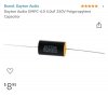
Found the reason why the right speaker had a weak super-tweeter. The oil cap was bad (rated at 4uF). Surprisingly the oil cap for the left was near spec but replaced both with new Dayton Audio caps. Both speakers now sound even. I’m going to listen for a week or so before I decide on how far to take the modifications/tweaking..... more to follow

463A0D03-6CFE-498C-8988-B9B515177DDD.jpeg
 
Yeah, PIO capacitors should always — without exception — be replaced before operating the speakers.

That metal-cased capacitor was not made for audio, it was made to run motors and was thus a commodity device of limited lifespan. Probably has PCBs, too. That's a bonus!

The original technology for PIO is abysmal compared to what is today inexpensively obtained. The manufacturing practices used for PIO were of routinely poor quality, the internal construction has poor connections (to leads and foil), the ESR is high, polymerization of the oil and corrosion have altered the properties, etc. The net result is that current moving in/out of the capacitor is dissipated as heat. If you think about how the capacitor functions, it's always charge shuttling in and out every half-cycle. Such is the nature of AC.

And if a capacitor shorts, which fortunately is a rare event, well, that's the end of the tweeter. Sometimes a midrange if a lot of low-frequency passes through the driver.

The driver is actually not a super-tweeter, just an ordinary cone tweeter. Goodmans tweeters do not have particularly good high-frequency performance. Just better than the whizzer cone on the full-range.
 
Yeah, impressive bass can be obtained from small ported systems.

Not to be negative, but I hear some distortion and resonance issues and peaking. All of which are fixable.

The source material may have issues, but I think it's the speakers. Listen at 8 to 12 seconds and 18 to 22 seconds to bracket the occurrence. Put the mouse on the pause button, close your eyes, and click when you hear the distortion. I think you'll hit the same points. It's continuous, but I most strongly hear it there.

Stuffing the enclosure and port could tame a fair bit of the resonance. diyAudio will have mountains of information on how to best accomplish that. Not expensive. I suggest adding a lining of thick cotton batting to the entire cabinet internals — including baffle, back, and add a flap hanging over the rear of the tweeter which is a hard surface — and around the port to reduce the internal reflections.

Another option is the aperiodic port (aka ARU or "Acoustic Resistance Unit") that I previously described. Goodmans used this on many of its more expensive loudspeakers and specifically recommended it for speakers like the Axiom 201, the bigger brother of your speaker. The omission of the ARU from your speaker was done as a cost-savings measure to meet the price point necessary to sell into that market segment. This is not fancy, just a piece of filter scrim. Goodmans put it in a frame and mounted it over a hole in the back of the cabinet.

Did you read Troels' page about chamfering? That also delivers some bang for the buck.

A member had a full-range Bozak speaker similar to what you have: 8" full-range driver with a tweeter, first-order filter (capacitor) for tweeter, nothing for woofer, ported, cabinet too small. I suggested he stuff the port which improved the sound, but the greatest improvement came from blocking the port. Bass output dramatically dropped, of course, but the objectionable distortion vanished. That was for an 8" system with a box far too small for deep bass response as the backwave pressure was muting the front wave.

You might have enough bass for near-field listening without the port and the sound might improve. Or maybe the stuffing slows the backwave enough to remove the issues.

Some experimentation is in order.
 
Yeah, impressive bass can be obtained from small ported systems.

Not to be negative, but I hear some distortion and resonance issues and peaking. All of which are fixable.

The source material may have issues, but I think it's the speakers. Listen at 8 to 12 seconds and 18 to 22 seconds to bracket the occurrence. Put the mouse on the pause button, close your eyes, and click when you hear the distortion. I think you'll hit the same points. It's continuous, but I most strongly hear it there.

Stuffing the enclosure and port could tame a fair bit of the resonance. diyAudio will have mountains of information on how to best accomplish that. Not expensive. I suggest adding a lining of thick cotton batting to the entire cabinet internals — including baffle, back, and add a flap hanging over the rear of the tweeter which is a hard surface — and around the port to reduce the internal reflections.

Another option is the aperiodic port (aka ARU or "Acoustic Resistance Unit") that I previously described. Goodmans used this on many of its more expensive loudspeakers and specifically recommended it for speakers like the Axiom 201, the bigger brother of your speaker. The omission of the ARU from your speaker was done as a cost-savings measure to meet the price point necessary to sell into that market segment. This is not fancy, just a piece of filter scrim. Goodmans put it in a frame and mounted it over a hole in the back of the cabinet.

Did you read Troels' page about chamfering? That also delivers some bang for the buck.

A member had a full-range Bozak speaker similar to what you have: 8" full-range driver with a tweeter, first-order filter (capacitor) for tweeter, nothing for woofer, ported, cabinet too small. I suggested he stuff the port which improved the sound, but the greatest improvement came from blocking the port. Bass output dramatically dropped, of course, but the objectionable distortion vanished. That was for an 8" system with a box far too small for deep bass response as the backwave pressure was muting the front wave.

You might have enough bass for near-field listening without the port and the sound might improve. Or maybe the stuffing slows the backwave enough to remove the issues.

Some experimentation is in order.
thank you! a few things to note...thinking out loud

1. Rick Rubin CD of Johnny Cash so distortion may be from brick walled mastering? I know Rubin liked to do this a lot.... he jacked the masters hard.

2. Back speaker panel not sealed tightly, I simply placed panel back into position and used some electrical tape and metal AC tape to hold into place to see if speakers were functioning equally but I know your points are valid and am weighing out all the options!

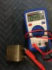
*Side note Dayton Audio crossover caps values were 3.88 uF and 4.02 uF so not happy with first one being 3 percent off. Im not sure if it meets tolerance but contacted vender to see what they say...

* Thinking out loud Philips sells ($20 each) a 3 inch 16 ohm tweeter Philips 3in Tweeter 16 OHMS Speaker 483524037002
 
Last edited:
As far as tolerance, 5% is generally considered to be acceptable tolerance. Did you purchase 1% parts? If you bought 5%, don't sweat the 3%. I build capacitors in bundles and can get them very close to theoretical, but in practice it's not that critical.

That distortion appears to be resonance and overloading. If you provide the name of the track I'll find a FLAC version for comparison.

You hear what I hear?

As far as that Philips tweeter, I cannot find a datasheet on it which is worrisome. The open back is highly troubling, as is the overall construction. It appears to be a cheap and shoddily made speaker for computers. I would not use it. Sigh. I know you specifically picked it for the 16 Ω impedance, but that's not the sole factor when selecting drivers. You would need to cover it with a flower pot, much like the Bozak midrange, to prevent cross-modulation and likely damage. I don't think it will do what you want and the high-frequency performance may be terrible. Again, no datasheet and no frequency response plots. I looked, too!

I visited the tweeter pages of both Parts Express and Madison Sound, neither has a 16 Ω tweeter. Grrr!

But all is not lost.

Two solutions present:
(1) Mixing impedances is possible, but generally not desirable. The big issue is that in a tube amplifier the load line will be altered and distortion will result. (Remember, an output transformer is an impedance matching device, so it is matching the output tube to the speaker.) Solid state does not care, particularly since the shift is from higher (16 Ω) to lower (8 Ω). But, having written that, the alteration is in a region where humans do not have especially acute hearing so it likely would be, if not undetectable, at least unobjectionable. The first-order rolloff means that most of the impedance hit is going to be above about 7,000 Hz, so should not be awful.​

(2) Since I wanted to use tubes, my conclusion was I had two options. Either (a) accept load-line distortion as per (1), or (b) take a wallet hit and double up on 8 Ω drivers, angle the two for better room dispersion, and then use an L-pad to balance against the midrange/woofer. Yeah, I know. WTF, dude! But few options present in the face of addressing peculiar impedance requirements. The L-pad is needed in either case, so it's not an extra expense.​

Silk domes are available for about $20 to $30 apiece, which is not a great solution if one requires four. I think going with (1) is your only reasonably priced option, and it permits spending more on a better driver.

I previously did some research into super-tweeters for Bozaks, which are 8 Ω so only one is required per speaker. The price for two would likely be excessive for your project. But this should give you an idea of what's involved:

I hesitate to recommend a driver I have not used. as I feel some responsibility if it does not work out. Many vendors, however, will permit you to return a driver for a refund. So you can always try a few and send back the rejects.

The tweeters I was considering, but which I have not tried, are in the Morel line:
Morel MDT 22
1-1/8" Soft Dome Neodymium Tweeter
80 Watts
88 dB / Watt
2,000 to 20,000 Hz
Price: $40.00
https://www.parts-express.com/pedocs/specs/277-062-morel-mdt-22-specifications.pdf

Morel MDT 39
1-1/8" Compact Dome Tweeter
80 Watts
88 dB / Watt
2,200 to 20,000 Hz
Price: $55.50
http://www.madisound.com/loudspeaker_specifications/MDT39-msc.pdf

Morel CAT 408
1-1/8" Compact Soft Dome Tweeter
120 Watts
89 dB / Watt
Price: $79.00
https://www.parts-express.com/pedocs/specs/277-086-morel-cat-408-specifications.pdf
Difference from the lower-cost MDT 39 is the "Hexatech" aluminum voice coil.
​
Note: the inclusion of a link to a vendor is not an endorsement of the vendor or its prices, and I have no connection to any business. I routinely purchase from Parts Express, an AK sponsor and have generally found its prices to be lower than other sources. I would have used Parts Express for the specifications, except in one case it did not supply the literature.

All of these tweeters use ferrofluid. Like many, I had bad experience with ferrorfluid tweeters in the 1980s, but those dissipated much higher power and were not as well made. I do not know the lifespan, but the reports are in excess of twenty years without abuse. The ferrofluid can be replaced.

For our purposes I suspect these drivers will have identical sound reproduction. The 39 has a slightly flatter response.

We also must discuss impedance compensation. This a fancy name for a filter, either band-pass (LRC) to notch out a resonance peak or a high-pass (RC) to reduce the rise in impedance with frequency. The resistor converts energy into heat. The filter basically is a frequency-dependent resistor, and it is placed in parallel with the driver, exactly like an L-pad. One need not use impedance compensation, of course, many nice-sounding speakers do not. The exact points are determined using frequency plots of the driver.

The MDT 39 rises from a nominal 8 Ω at 8,000 Hz to 13 Ω at 20,000 Hz. This may be tamed with a RC filter aka Zobel. Separate discussion. That's a refinement, and many speakers, again, do not use it. We need not worry about the resonance peak, as energy is not going into the tweeter in that band, as it would if the tweeter were being used in a traditional configuration.
 
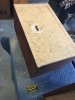
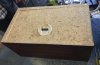
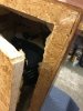
In addition, Id like to get some walnut plywood in the back and am looking for how to remove the outer edge (pressed wood). Some kind of adhesive was used. Not budging. Im thinking maybe a heat gun to loosen the adhesive but not burn the wood? don't know just thinking out loud here...A2FF431F-D585-4791-BC95-4E45CDE81C4D.jpeg56C0B127-40D4-4FC7-BF82-3976764D72D8.jpeg
 
It will be impossible to disassemble the cabinet without severely compromising the integrity of the cabinet, if not totally ruining it.

The cabinet was likely built using a rabbet joint — back has a narrow band removed around all four sides and fits into a depressed lip area in the cabinet sides — and the entire shebang was then together glued. Yeah, I know. I have the EE series which was in this fashion fabricated. Horrible way to build a speaker which would need a crossover rebuild, but nobody ever thought that far in the future.

This is why the cabinet cannot be easily disassembled, or even without horrendous damage. I urge you to not attempt this, particularly as a simpler solution exists.

I again suggest mounting wooden cleats to the remaining lip as an internal frame, such that the cleats outwards extend under the lip permitting the back to simply drop into the gap and rest on top of the cleats. The back may then be screwed to the cleats using wood screws. Done. I suggest using screws and glue to secure the cleats to the remaining lip. Counter-sunk wood screws are great, but you could also use machine screws with washers on both sides if you prefer.

Cleats is a very standard approach to securing cabinet backs, speaker backs, and lids to wooden boxes, etc. and it's a good one. Similar to constructing a rabbet joint without having to cut away any material.

The back appears to be thick enough and robust enough to not have structural issues.
 
Don't worry about appearance; it's the rear and it's going against a wall. By the time anyone notices you won't be around to be hassled about your cabinet choices. (I'm assuming you like these enough to keep them.)
 
I agree with Retrovert about those cabinets not being easily modified. It would almost be simpler to build new cabinets than to do what you propose.

Refer to my post #2. You can see the stips I glued inside. I glued 4 strips around the opening. I used a gasket so that the cut-out back is sealed when screwed in place.

If you really want a walnut back, then veneer the back. It would be the simplest solution if you must hide the chipboard rear.
 
Back
Top Bottom