• The move to the new server is done. There are some software and database maintenance updates in process. This has us passing the hat around to help out. We appreciate any donations. Seriously, even a dollar helps. The payment page may be found here - https://www.audiokarma.org/support.html

Grundig SO 132US transformer question.

BeefJerky666

New Member
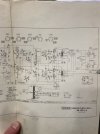
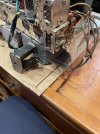
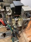
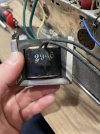
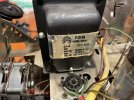
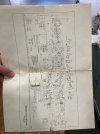
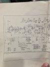
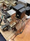
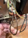
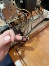
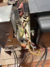
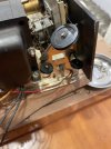
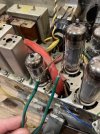
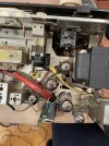
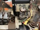
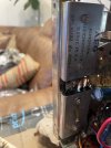
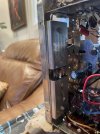
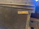
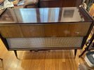
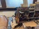
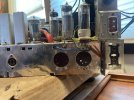
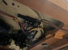
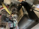
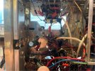
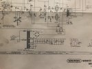
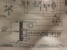
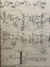
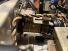
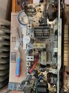
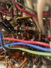
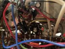
Hello! This is my first post so I will try my best to provide as much information as possible. I have a Grundig SO 132 stereo console which works mostly but I can’t get over that there seems to be an extra transformer and a loose tube. I was lucky to find the electrical schematics(IN ENGLISH!) and sure enough the wiring is suspect. The rectifier appears to be missing as well and I just don’t understand what’s going on and how this worked. As I recapped the console everything started working but towards the end I was having some power issues which is where I’m at now. The radio has no sound but the record player works perfectly. I am not well versed in reading electrical schematics and don’t want to burn out any components. If someone could take a look for me I’d be wildly appreciative. Here are some photos. please let me know if any other photos, information, or whatever else is helpful. Thanks :)
 

Attachments

  • IMG_0652.jpeg
    IMG_0652.jpeg
    111.6 KB · Views: 28
  • IMG_0609.jpeg
    IMG_0609.jpeg
    148.6 KB · Views: 27
  • IMG_0612.jpeg
    IMG_0612.jpeg
    127.2 KB · Views: 27
  • IMG_0616.jpeg
    IMG_0616.jpeg
    95.6 KB · Views: 24
  • IMG_0619.jpeg
    IMG_0619.jpeg
    122.6 KB · Views: 25
  • IMG_0653.jpeg
    IMG_0653.jpeg
    104.3 KB · Views: 24
  • IMG_0651.jpeg
    IMG_0651.jpeg
    109.5 KB · Views: 22
  • IMG_0605.jpeg
    IMG_0605.jpeg
    129 KB · Views: 25
Register to hide this ad
I can see that some of the wiring on these photos isn’t the best. When I get home I’ll try to get a few more that show the wiring clearer.
 
Here are a few more. I suspect the larger transformer is not the original and the second one was added along with it.
 

Attachments

  • IMG_0606.jpeg
    IMG_0606.jpeg
    89.9 KB · Views: 16
  • IMG_0608.jpeg
    IMG_0608.jpeg
    127.2 KB · Views: 15
  • IMG_0610.jpeg
    IMG_0610.jpeg
    96.2 KB · Views: 14
  • IMG_0611.jpeg
    IMG_0611.jpeg
    96 KB · Views: 15
  • IMG_0613.jpeg
    IMG_0613.jpeg
    129.2 KB · Views: 15
  • IMG_0615.jpeg
    IMG_0615.jpeg
    134.5 KB · Views: 16
  • IMG_0618.jpeg
    IMG_0618.jpeg
    120.9 KB · Views: 16
Whatever you do, do NOT plug this in and try to power it up!

Neither the large power transformer held to the chassis by one bolt and the "extra" floating transformer are original. Best guess is that the original power transformer failed and some very unskilled "tech" has subbed in two PT's to replace it. The large PT, per the pasted on schematic, looks to have the high-voltage source winding and a 6.3V heater winding. The smaller "floating" transformer may be another heater winding, but not really sure. The primaries of both of these transformers are wired evidently directly to the line cord with some very janky connections. Who knows if the installed transformers are even close to the voltage and current ratings needed, let alone whether they are wired at all properly into the circuit.

The original power rectifier tube that may have gone in the open octal socket is missing and some small 9 pin tube and socket has been perilously soldered to the chassis with what looks to be a nine-pin rectifier tube in it--can't tell for sure from the pics. The schematic shows a PT with three windings: HV, tube heaters, and another that I can't be sure of because of the lack of clarity on the schematic pic you sent.

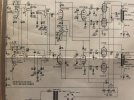
Another puzzling aspect is that the schematic you provided shows a solid state diode bridge rectifier for the HV, not tubes. Is this the correct schematic for the unit?

Anyway, this is a real mess and you really need to puzzle over it and try to return to something like stock configuration before you try to use it. I'm not even going to try to guess what's going on with this one at this stage beyond the above.

Dave
 
I agree with Dave - the added PT and a filament transformer.

Grundig didn’t use tube rectifiers during this period (or octal tubes) so that’s also been added.

This one will be doubly difficult to cut your teeth on. German build style is tough enough to figure out and then you’ve got the riddle of that dubious work. Oy.

There are a LOT of similar Grundigs that can be made to fit your cabinet. I’d be on the lookout for a donor.
 
Last edited:
Original would have been a bridge rectifier, the HV transformer looks like it would have been meant to pair with a tube rectifier and I'm guessing thats what someone did. Why they didn't use it in a full wave grounded center tap config is anyone's guess but this is some serious bodge work for sure.

I can't make out what that other secondary on the original transformer would have been powering. Top is HV, middle is the tubes, bottom is ?? Possibly thats what the extra little trafo is doing.

This one will be doubly difficult to cut your teeth on. German build style is tough enough to figure out and then you’ve got the riddle of that dubious work. Oy.

There are a LOT of similar Grundigs that can be made to fit your cabinet. I’d be on the lookout for a donor.


have to agree here. Not impossible to fix, but this is definitely not what I'd start with if you don't already have some tube experience. Un-doing hack work is difficult enough, add to that how hard German stuff can be to work on anyway and its a real headache.
 
That octal socket is riveted in--looks original. Looking at the schematic, there's an 8 pin connector shown between the audio output transformers and the speakers. This octal socket is probably where the plug to the speakers goes. Best guess.
 
Thanks for the replies already. So the unit does work… I have powered it on and recapped the entire thing. Whatever is going on with the sketchy wiring is operational even though I don’t trust it. Here is the bridge rectifier that’s mounted to the underside, right below the power transformer. Would I be able to find a modern replacement for the original one that used to be installed? Also, I’m to understand that loose tube is a replacement for the bridge rectifier?
 

Attachments

  • IMG_0657.jpeg
    IMG_0657.jpeg
    87.2 KB · Views: 19
  • IMG_0656.jpeg
    IMG_0656.jpeg
    114.8 KB · Views: 17
  • IMG_0655.jpeg
    IMG_0655.jpeg
    111.2 KB · Views: 17
  • IMG_0654.jpeg
    IMG_0654.jpeg
    156 KB · Views: 18
  • IMG_0658.jpeg
    IMG_0658.jpeg
    152.6 KB · Views: 18
  • image.jpg
    image.jpg
    108.4 KB · Views: 17
That octal socket is riveted in--looks original. Looking at the schematic, there's an 8 pin connector shown between the audio output transformers and the speakers. This octal socket is probably where the plug to the speakers goes. Best guess.
There are two 8-pin connectors. The colored one connects to the speaks and to what I believe is a connection for additional speakers, the brown one connects to the underside of the record player works
 

Attachments

  • IMG_0659.jpeg
    IMG_0659.jpeg
    123.7 KB · Views: 15
  • IMG_0660.jpeg
    IMG_0660.jpeg
    135.7 KB · Views: 15
  • IMG_0662.jpeg
    IMG_0662.jpeg
    69.4 KB · Views: 15
Original would have been a bridge rectifier, the HV transformer looks like it would have been meant to pair with a tube rectifier and I'm guessing thats what someone did. Why they didn't use it in a full wave grounded center tap config is anyone's guess but this is some serious bodge work for sure.

I can't make out what that other secondary on the original transformer would have been powering. Top is HV, middle is the tubes, bottom is ?? Possibly thats what the extra little trafo is doing.


have to agree here. Not impossible to fix, but this is definitely not what I'd start with if you don't already have some tube experience. Un-doing hack work is difficult enough, add to that how hard German stuff can be to work on anyway and its a real headache.
The secondary transformers green wires head to the tube(344 on the top) directly next the the main transformer. They’re connected to the same prong that has those other green wires coming off of it, the ones that go into the red sleeve.
 

Attachments

  • IMG_0663.jpeg
    IMG_0663.jpeg
    101.1 KB · Views: 12
  • IMG_0664.jpeg
    IMG_0664.jpeg
    138 KB · Views: 12
Right, but i can't work out what that actually does


The horizontal octal on top is probably an eye tube. EM34 I'd wager
 
Right, but i can't work out what that actually does


The horizontal octal on top is probably an eye tube. EM34 I'd wager
Would a better photo of the schematic help? I’m not sure what my next step should be. Would love to get this back to a more original state lol

Yes. That’s exactly what’s there.
 

Attachments

  • IMG_0665.jpeg
    IMG_0665.jpeg
    150.4 KB · Views: 8
  • IMG_0666.jpeg
    IMG_0666.jpeg
    163 KB · Views: 8
  • IMG_0667.jpeg
    IMG_0667.jpeg
    132.7 KB · Views: 8
  • IMG_0668.jpeg
    IMG_0668.jpeg
    157.9 KB · Views: 8
  • IMG_0669.jpeg
    IMG_0669.jpeg
    83.7 KB · Views: 9
Looks like the other things are the two ecc83. Not sure why those are on their own winding, or if they need to be.
 
I made a google drive with the schematic photos. I realized they don’t upload with a high resolution so hopefully this is better.


Do you think I should try to replace the tube rectifier with a different one? Maybe try to reattach the old one back up? I’d like to replace the power transformer too.
 
Last edited:
Yes, those schems are much better.

Does yours have four EL95 power tubes? I can’t tell. Some of the US versions had a pair of ELL80 tubes.

That original rectifier is selenium, and they usually get replaced with a new silicon full wave bridge rectifier (or four diodes) because they are cheap and reliable. I put a 100 ohm resistor after the DC+ to lower the voltage a bit and protect the rectifier.

A replacement PT would allow you to go about reconstructing the crime scene and put things back to right. Not an easy job, as we were saying above, but not impossible.
There are many Grundigs from this period that would be a suitable donor. I have one from an SO240 that might work. Checking the tube count is the place to start.

You say that it works, or the phono works but radio doesn’t. If the phono works, that means the power supply, power amp and preamp are all functioning. You could solder and shrink wrap those twisted leads and continue to observe/measure and listen to it as you accumulate parts.

The radio circuit is the same or very similar on many models from this time period. Usually all they need is clean tube sockets and pins, clean switch controls, maybe a tube or two, and paper caps replaced. And an antenna.
 
Yes, those schems are much better.

Does yours have four EL95 power tubes? I can’t tell. Some of the US versions had a pair of ELL80 tubes.

That original rectifier is selenium, and they usually get replaced with a new silicon full wave bridge rectifier (or four diodes) because they are cheap and reliable. I put a 100 ohm resistor after the DC+ to lower the voltage a bit and protect the rectifier.

A replacement PT would allow you to go about reconstructing the crime scene and put things back to right. Not an easy job, as we were saying above, but not impossible.
There are many Grundigs from this period that would be a suitable donor. I have one from an SO240 that might work. Checking the tube count is the place to start.

You say that it works, or the phono works but radio doesn’t. If the phono works, that means the power supply, power amp and preamp are all functioning. You could solder and shrink wrap those twisted leads and continue to observe/measure and listen to it as you accumulate parts.

The radio circuit is the same or very similar on many models from this time period. Usually all they need is clean tube sockets and pins, clean switch controls, maybe a tube or two, and paper caps replaced. And an antenna.
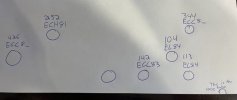
Hmmm so mine doesn’t seem to have any of those. Here is something quick I threw together. I’ll try to get it more accurate later today by measuring the height of the tubes to potentially match them up better. Some of the letters/numbers have rubbed off.

Yes. Currently the radio doesn’t get a signal but it has worked perfectly in the recent past. I think I did something replacing the last capacitor. Not sure just yet.

Would that power supply be something I could purchase from you?

I want to say again I really appreciate the time everyone is taking to help me here! :) it means a bunch.
 

Attachments

  • IMG_0678.jpeg
    IMG_0678.jpeg
    164.3 KB · Views: 10
  • IMG_0677.jpeg
    IMG_0677.jpeg
    33.6 KB · Views: 10
  • IMG_0676.jpeg
    IMG_0676.jpeg
    143.3 KB · Views: 12
Last edited:
That’s a good start. I do wonder if what you have labelled as EL84 are actually ELL80s, which are two pentodes in one bottle. The difference is single-ended vs push-pull, and needs to match up correctly with the output transformers.

See if you can get a good photo of the business end of those two power tube sockets. Particularly if there are OT wires coming into pins 3 and 8. Those are the plate connections. The control grids would be 2 and 6, and pin 7 would have a cathode resistor and an electrolytic capacitor connected to if….. if it was made for an ELL80.

If they are wired for two single EL84s you have the OT/plate connection on 7, control grids to 2 and a cathode resistor and bypass cap on 3.

Lets figure out what you’ve got.
 
That’s a good start. I do wonder if what you have labelled as EL84 are actually ELL80s, which are two pentodes in one bottle. The difference is single-ended vs push-pull, and needs to match up correctly with the output transformers.

See if you can get a good photo of the business end of those two power tube sockets. Particularly if there are OT wires coming into pins 3 and 8. Those are the plate connections. The control grids would be 2 and 6, and pin 7 would have a cathode resistor and an electrolytic capacitor connected to if….. if it was made for an ELL80.

If they are wired for two single EL84s you have the OT/plate connection on 7, control grids to 2 and a cathode resistor and bypass cap on 3.

Lets figure out what you’ve got.
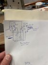
So this is what I got right now. I tried to make a sketch of the pins. Photos aren’t really working… too much going on to get a decent view of anything. I’ll try again later when I can find more light source. I probably didn’t do this diagram well. Hopefully it’s something you can make out. If not I’ll get more/better diagrams after work.

Edit: part of me is also thinking I may have written down the pins backwards… 1=9, 2=8, etc.
 

Attachments

  • IMG_0683.jpeg
    IMG_0683.jpeg
    132 KB · Views: 4
  • IMG_0684.jpeg
    IMG_0684.jpeg
    123.3 KB · Views: 4
  • IMG_0685.jpeg
    IMG_0685.jpeg
    117.6 KB · Views: 4
  • IMG_0682.jpeg
    IMG_0682.jpeg
    82 KB · Views: 4
Could you add that schematic to your Google Drive? The link is not opening for me.
Schematics in Deutsch are not a problem. You’ll pick up a few new words like Linker Canal and Auf.

You got the pins right - counter clockwise when looking at the terminals, start after the gap.

Kinda looks like a single EL84s for each channel, as you said. I wanted to verify before proceeding as it affects what Transformers are used.
 
Back
Top Bottom