• The move to the new server is done. There are some software and database maintenance updates in process. This has us passing the hat around to help out. We appreciate any donations. Seriously, even a dollar helps. The payment page may be found here - https://www.audiokarma.org/support.html

Grundig SO 132US transformer question.

Could you add that schematic to your Google Drive? The link is not opening for me.
Schematics in Deutsch are not a problem. You’ll pick up a few new words like Linker Canal and Auf.

You got the pins right - counter clockwise when looking at the terminals, start after the gap.

Kinda looks like a single EL84s for each channel, as you said. I wanted to verify before proceeding as it affects what Transformers are used.
Added. Tomorrow I should be able to get a clearer copy from radio museum.
 
That one looks close if not right on. A cleaner version would be nice but I think you can work with this to get you the rest of the way.

I will send you a message about the SO240 trannie including mounting hole spacing.

For the radio, follow your instincts and go back to the last cap you installed.
 
A new schematic has been uploaded, Grundig SO 132 2/2. Have to wait a little longer to get the first half. Once again it’s a bit different from the others but very similar and more importantly, much clearer.

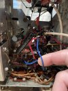
So the next thing I need to get is this to remove that loose tube rectifier. However the tube has 5 connections to it… 2 are from the transformer, the black wire is to the chassis, and the other two I’m not sure about. One is this blue wire that goes to this, not sure what this black tube is.
 

Attachments

  • IMG_0692.png
    IMG_0692.png
    155.6 KB · Views: 6
  • IMG_0691.jpeg
    IMG_0691.jpeg
    128.2 KB · Views: 6
Good news on the schem. On your Google Drive it would help (me at least) to have the ones that are not it deleted from the drive. Start with the ones that use four EL95s; we know its not one of those.

As for the leads from the tube socket, follow the other two leads to see where they go.

The black tube is a 1K resistor 4W probably in the power supply, possibly between the two main filter caps. Once you settle on a schematic you should be able to find it.

That bridge rectifier is the right idea but overkill, especially on price. I use mouser.com for parts like this. Offhand I see something like this. However, last time I needed a Full Wave Bridge I used four of these (which can also be considered overkill, but cheap.


.

 
Good news on the schem. On your Google Drive it would help (me at least) to have the ones that are not it deleted from the drive. Start with the ones that use four EL95s; we know its not one of those.

As for the leads from the tube socket, follow the other two leads to see where they go.

The black tube is a 1K resistor 4W probably in the power supply, possibly between the two main filter caps. Once you settle on a schematic you should be able to find it.

That bridge rectifier is the right idea but overkill, especially on price. I use mouser.com for parts like this. Offhand I see something like this. However, last time I needed a Full Wave Bridge I used four of these (which can also be considered overkill, but cheap.


.
Ok. Google drive is updated to only include the two possible ones. Will order the new rectifier shortly and I should already have a correct resistor lying around somewhere for the new full wave bridge rectifier.
 
Between the schematics two glaring differences are that the SO132 uses only three radio tubes and has an octal eye tube (as gadget noticed earlier) where the 132a has four radio tubes and a noval eye tube.

SO132
ECC85 > ECH81 > EBF89 then the ECC83 preamps
EM34 octal eye

SO132a
ECC85 > ECH81 > EF89 > EABC80 then the ECC83s
EM84 noval eye

Does your set line up with one of these?
 
Between the schematics two glaring differences are that the SO132 uses only three radio tubes and has an octal eye tube (as gadget noticed earlier) where the 132a has four radio tubes and a noval eye tube.

SO132
ECC85 > ECH81 > EBF89 then the ECC83 preamps
EM34 octal eye

SO132a
ECC85 > ECH81 > EF89 > EABC80 then the ECC83s
EM84 noval eye

Does your set line up with one of these?
I removed the schematic that isn’t correct. The one that’s right is the EBF89 as it also has the EM34 magic eye.

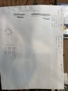
I went through and tested the voltage of the transformers that are currently installed and this is what I got. I believe the green wire that’s connected to the rectifier tube isn’t supposed to be there.

I was having trouble testing the dc voltage on the blue wire so the 212v might be off
 

Attachments

  • image.jpg
    image.jpg
    73.1 KB · Views: 2
What type is the rectifier? Is it a 7-pin?

A tube rectifier socket will have 2 wires for its filament (low AC volts between them), 2 wires for its plates (high AC volts between them), and a cathode (high DC volts with respect to ground).

Sometime the cathode and filament share a pin.
 
What type is the rectifier? Is it a 7-pin?

A tube rectifier socket will have 2 wires for its filament (low AC volts between them), 2 wires for its plates (high AC volts between them), and a cathode (high DC volts with respect to ground).

Sometime the cathode and filament share a pin.
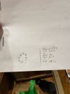
Yes it’s 7-pin. This is how it’s laid out
 

Attachments

  • image.jpg
    image.jpg
    62.5 KB · Views: 6
Possibly an EZ90, what we ‘mericans call 6X4. Very common tube but a little light for your set’s tube count and draw. But sounds like it works.

Your pin 7 voltage agrees. This is the cathode, providing DC voltage for the tubes.

Switch your meter to AC volts and with one lead on 1 and the other lead on 6, you should see the VAC that the high voltage secondary of the transformer is sending the tube. The “input” so to speak.

With leads on 3 and 4 should be your filament voltage 6.3 VAC ideally.


Last edited:
Looks like you got plenty of help. Skimming this thread, maybe the original owner thought that the main power transformer was getting too hot and wanted to relieve that somehow.

I would just connect all 6.3 volt tubes to the 6.3 volt tap on the power transformer. I would also do away with that tube rectifier and and just add a diode in place of the bridge and use the HV tap on the power transformer.

4 wires on the rectifier is easy to explain. There are two wires for the heater and two wires for the high voltage. The black wire connected to the chassis is normally the center tap.

Since you already recapped this, it will already run a lot cooler.

Good luck with this.

Just make sure you use your meter and make sure there are voltages coming out of all secondary wires on the main power transformer.

Just my .02 cents.
 
Last edited:
Back
Top Bottom