SansuiSushi
Active Member
A friend decided to buy a SA-9100 unseen and having no amp restoration experience, and me having a few sucesses under my belt, he passed it to me to fix for him.
Now of all the amps that have sat upon my work bench in its various forms, I have never seen an amplifier with this degree of unprofessional cowboy repairs. I hope that some of you find these pictures entertaining.
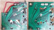
Ouch, who did the work Edward Sissorhands?! This is after I cleaned it up see below as it looked basically the same as board 2
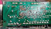
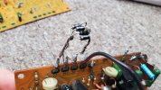
Too many things happening here!

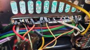
A cheap speaker wire to join the the broken solder connection

I think "Series and paralel were mixed up here"
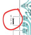
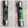
Spot the missing corner? How does that even happen? Perhaps the 'tech', (or unqualified 'soldering iron holder' in this case) dropped it and wheeled his chair over it as he turned to find it or pick it up.
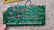
What ideas can you come up with as to what might have happened there? Write them below!
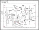
While I dont feel "out of my depth" with this one per say, its new to me certainly, and transistor replacement advice would ve MOST hepful. So I would like to consult and confer with others, who maybe know of devices, products, or techniques that I may not yet be aware of, that could help solve the issues with this amplifer as I go through it.
As it stands now both amp boards have been removed from the amplifier, THANKFULLY to the amplifier gods, the preamp section with it's complex switching remains untouched, and aside drom a few broken wires, likely works. Now yes, I did check the amplifier powered up before starting on it and it did even went out of protection, this was on a very limited current via a DBT as is standard proceedure.
Now I must admit, I did forego the initial internal visual inspection, my friend was there and wanted to know if it even powered up, and its his amp his choice, this is absolutely an error on my part, you should ALWAYS do a visual inspection of this equipment before it seen any plug juice.
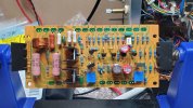
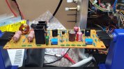
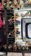
Its a nicely made amplifier which is somewhat of a bugger to work on due essentially a powerful TOTL amplifier being crammed into a standard amplifier size, lots of wire runs, lots of mechanical switching with large 4 gang rotary switches, some of you may be familiar with it.
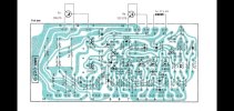
Now the difference between the two boards is stark, I have stripped, cleaned and removed loose tracks,
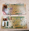
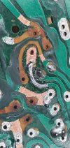
I dislike my "repair here", I can be better, thoughts? How would you appoach this corner?
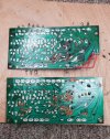
I've somewhat started rebuilding one of them, pending what to do with the other, I made a repair rough, but to see how it would turn out, ideally I want to remake the entire board, but I'm not sure how to go about that or if it's worth it vs the work involved to repair the tracks etc. I have half the tools for that those I dont have I ordered, some self adhesive copper tape UV light for curing the green solder mask.
Would also like to replace the pins perhaps with some sort of socket system so the boards can more easily be removed to be work on in the future, given how weak the traces are that may or may not be a good thing.
Looking forward to your thoughts, its a lovely amp thats been treated badly.. lets fix it up.
Now of all the amps that have sat upon my work bench in its various forms, I have never seen an amplifier with this degree of unprofessional cowboy repairs. I hope that some of you find these pictures entertaining.
Ouch, who did the work Edward Sissorhands?! This is after I cleaned it up see below as it looked basically the same as board 2
Too many things happening here!
A cheap speaker wire to join the the broken solder connection
I think "Series and paralel were mixed up here"
Spot the missing corner? How does that even happen? Perhaps the 'tech', (or unqualified 'soldering iron holder' in this case) dropped it and wheeled his chair over it as he turned to find it or pick it up.
What ideas can you come up with as to what might have happened there? Write them below!
While I dont feel "out of my depth" with this one per say, its new to me certainly, and transistor replacement advice would ve MOST hepful. So I would like to consult and confer with others, who maybe know of devices, products, or techniques that I may not yet be aware of, that could help solve the issues with this amplifer as I go through it.
As it stands now both amp boards have been removed from the amplifier, THANKFULLY to the amplifier gods, the preamp section with it's complex switching remains untouched, and aside drom a few broken wires, likely works. Now yes, I did check the amplifier powered up before starting on it and it did even went out of protection, this was on a very limited current via a DBT as is standard proceedure.
Now I must admit, I did forego the initial internal visual inspection, my friend was there and wanted to know if it even powered up, and its his amp his choice, this is absolutely an error on my part, you should ALWAYS do a visual inspection of this equipment before it seen any plug juice.
Its a nicely made amplifier which is somewhat of a bugger to work on due essentially a powerful TOTL amplifier being crammed into a standard amplifier size, lots of wire runs, lots of mechanical switching with large 4 gang rotary switches, some of you may be familiar with it.
Now the difference between the two boards is stark, I have stripped, cleaned and removed loose tracks,
I dislike my "repair here", I can be better, thoughts? How would you appoach this corner?
I've somewhat started rebuilding one of them, pending what to do with the other, I made a repair rough, but to see how it would turn out, ideally I want to remake the entire board, but I'm not sure how to go about that or if it's worth it vs the work involved to repair the tracks etc. I have half the tools for that those I dont have I ordered, some self adhesive copper tape UV light for curing the green solder mask.
Would also like to replace the pins perhaps with some sort of socket system so the boards can more easily be removed to be work on in the future, given how weak the traces are that may or may not be a good thing.
Looking forward to your thoughts, its a lovely amp thats been treated badly.. lets fix it up.
Attachments
Last edited: