• Please note that Audiokarma will be offline briefly for updates early on Monday morning, September 28th.

Hacked up Pioneer SA-9100 restoration

I think you did a great job repairing those broken traces. I'd never considered using copper foil, will look into it next time.

You might look at some uv cureable solder mask and a uv flashlight. I bought these when I was working on old 1980's Macs. Leaking electrolytic caps, exploded batteries, ugh... lol
 
Alright time to revive this thread from the crypt and ask for advice again.
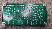
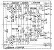
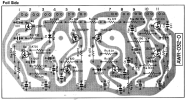
After a long break I am back at it once again trying to get this SA9100 back up and running, putting a parts list together working on the AWR-032 A power supply board.

media_20240313_180316_6798942870883781086.jpg
media_20240313_180316_7825263379366311054.jpgmedia_20240313_180316_8708840814214357996.jpg

Transistors... Transistors...

Q1Transistor2SD313512-KSC2073TU (In Stock In basket @ Mouser)
Q2Transistor2SB507512-KSA940TU (Installed)
Q3Transistor2SC945512-KSC2383YTA (Installed)
Q4Transistor2SA720512-KSA1013YBU (Installed)
Q5Transistor2SC1318512-KSC2690YTA (Installed)
Q6Transistor2SA720512-KSA1120AYS (OUT OF STOCK)
Q7Transistor2SC1318512-KSC2690AYS (Installed)
Q8Transistor2SA720512-KSA1220AYS (OUT OF STOCK)
D1Zener DiodeWZ-13013V500mW512-1N4743ATR (In Stock In basket @ Mouser)
D2Zener DiodeWZ-13013V500mW512-1N4743ATR

Cant find the KSA1120 or KSC1220, need an alternative they all seem to be replacing a 2SA720 so maybe I made a foobar and could just use KSA1013? My hunt around the forums suggests not in two separate locations here and here.

Parts list can be seen here (Google Sheets) pretty much done except for the transistor and electrolytic caps, which I am finding difficult to get Nichicon UPW / UPM with 5mm lead spacing as per the board, went with a Chemi-Con KY for the two 100uf 50V caps C1, C2.

Also had a query about the resistors on the board, there were a few covered by a braiding, are these fusible? R1, R2, R24.


brave_7HINerdEb3.png
brave_ePwQSB3qlr.png
 
If you look on eBay you should be able to find the transistors you need. The Affinity for Artifacts store has them, I believe.

Take your time, check and double check component placement and polarity on the board. Check and double check the wiring when you’re reconnecting the board. Good luck!
 
Thank you for that suggestion, I am in the UK though so I really need something from Mouser, where it is not currently in stock, I need to look at the spec sheets again for the original and try and match it. I have already installed two KSC2690A on the positive side of things, Ideally would like to use the correct pairing (does this matter?)

2SA720
Material of Transistor: Si
Polarity: PNP
Maximum Collector Power Dissipation (Pc): 0.4 W
Maximum Collector-Base Voltage |Vcb|: 60 V
Maximum Collector-Emitter Voltage |Vce|: 40 V
Maximum Emitter-Base Voltage |Veb|: 5 V
Maximum Collector Current |Ic max|: 0.5 A
Max. Operating Junction Temperature (Tj): 175 °C
Transition Frequency (ft): 100 MHz
Collector Capacitance (Cc): 10 pF
Forward Current Transfer Ratio (hFE), MIN: 90
 
Could I use a KSA1013YBU? The package size difference makes me wince a bit!

T KSA1013
Material of Transistor: Si
Polarity: PNP
Maximum Collector Power Dissipation (Pc): 0.9 W
Maximum Collector-Base Voltage |Vcb|: 160 V
Maximum Collector-Emitter Voltage |Vce|: 160 V
Maximum Emitter-Base Voltage |Veb|: 6 V
Maximum Collector Current |Ic max|: 1 A
Max. Operating Junction Temperature (Tj): 150 °C
Transition Frequency (ft): 15 MHz (BAH)
Collector Capacitance (Cc): 35 pF (Bah)
Forward Current Transfer Ratio (hFE), MIN: 60 (BAH)
 
Could I use a KSA1013YBU? The package size difference makes me wince a bit!

T KSA1013
Material of Transistor: Si
Polarity: PNP
Maximum Collector Power Dissipation (Pc): 0.9 W
Maximum Collector-Base Voltage |Vcb|: 160 V
Maximum Collector-Emitter Voltage |Vce|: 160 V
Maximum Emitter-Base Voltage |Veb|: 6 V
Maximum Collector Current |Ic max|: 1 A
Max. Operating Junction Temperature (Tj): 150 °C
Transition Frequency (ft): 15 MHz (BAH)
Collector Capacitance (Cc): 35 pF (Bah)
Forward Current Transfer Ratio (hFE), MIN: 60 (BAH)
Seems overkill but will most likely work.
since your´e in Europe might as well check out BD140, be aware the different pinout
 
Last edited:
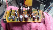
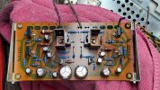
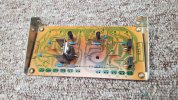
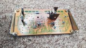
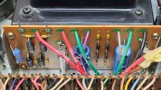
Back at it again... Rebuilt the power supply boards all new components on both boards.

AWR-031 (B)
20240403_160004.jpg

AWR-032 (A)

20240403_155920.jpg
20240403_155924.jpg

I have the boards installed, powered on with no load, ie the preamp, control board , relay, speaker protection etc is not connected to power, only the power boards themselves.

For the AWR-032 board this is:
Pin 1 - Common Ground/Earth
Pin 6 - Negative Rail -
Pin 7 - Positive Rail +

This is on a DBT to prevent any damage while testing occurs.

The main filter caps (original 15,000uF) are in circuit, though this is a split power supply. The OUTPUT voltages of each board basically check out good with no load, BUT I am getting a fair bit of warmth though my fingers are surprisingly numb I can feel the heat, seems to be coming from R1, R2, D1, Q1, Q2, and I'm not sure if those are heating up C1, C2 but it appears they also get warm, which is my main concern as I've never had a warm capacitor so something isn't right.

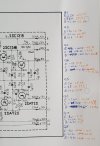
I'm a bit stuck as how to tackle this as the voltages are all stable. I've gone through and checked all transistor voltages with reference to ground. Reference from schematic in italics, my reading in orange... Edit (picture is easier)
20240403_170545.jpg

Q1 NPN
E 42V
C 56V
B 42.6V
Q2 PNP
E -42V
C -56.5
B -42.6
Q3 NPN
E 13V
C 42.6V
B 13.6V

Q4 PNP
E -13V
C -42.6
B -0.6V

Q5 NPN
E 24V
C 29V
B 24.6V

Q6 PNP

E -24V
C -30V
B -24.6

Q7 NPN
E 16V
C 20.5V
B 16.6V

Q8 PNP
E -16V
C -20.5V
B -16.6V


Question is what am I missing?

 
I feel bad I didn't see this, I have a full set of all those boards already disarticulated except the pre stages. wish I would have seen this sooner
 
Back
Top Bottom