• Please note that Audiokarma will be offline briefly for updates early on Monday morning, September 28th.

Hammond AO-35 HiFi Conversion Help

punkzter

Brad
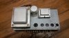
I was given a Hammond AO-35 (and a Hammond AO-29) that I would like to convert into a standalone amp. It's mono, but a friend has said that he can get me another once I have this one going.

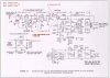
I've attached the schematic to this message. I wondered if anyone here has any experience with this conversion?

I know that, for starters, I need to work on the input impedance portion of the circuit. I read through an article where the user converted this into a guitar amp, but I was hoping that someone could explain how to alter the circuit so that it would work for a hifi input.

The output transformers are 8 ohm, which will be an issue in the long run for me, as my favorite speakers are 4 ohm. I would consider changing the OPT, especially if what I've read is true, and these organ amp OPTs have limited frequency response.

I am pretty sure that I have it figured out enough to hook it up to a signal generator and see how it responds. But I hope to have my friend with me before I fire it up.

Other than that, are there any suggestions? I'm new to this, so would appreciate any help.

Here is a link to the schematic:
https://tornadoalleyfx.files.wordpress.com/2015/04/ao35.jpg
 

Attachments
  • ao35.jpg
    ao35.jpg
    84.4 KB · Views: 66
  • 20170207_190218.jpg
    20170207_190218.jpg
    69.4 KB · Views: 62
  • 20170207_190238.jpg
    20170207_190238.jpg
    51.2 KB · Views: 55
  • 20170207_190305.jpg
    20170207_190305.jpg
    97.1 KB · Views: 57
Last edited:
Register to hide this ad
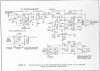
So, this schematic is from a site where they converted the amp to a guitar amp. It's different, but I'm curious to know if these changes might be good.
 

Attachments

  • AO35_3.jpg
    AO35_3.jpg
    85.6 KB · Views: 23
Generally, yes, but I would not reduce the 2.2M negative feedback resistor. That is reduced to get the amp more gain and more grit, which is what guitar players like. Not so good in hifi.

By the way, this is the chassis that got Dr. Z amps up and running, with his Carmen Ghia amps. Great story, and he gives an interesting interview. Worth the search.
 
I do have a scope, and a signal generator. Oh, and I do know to make sure I have a load on the output transformer. I have some 8 ohm 50 watt resistors.
 
Generally, yes, but I would not reduce the 2.2M negative feedback resistor. That is reduced to get the amp more gain and more grit, which is what guitar players like. Not so good in hifi.

By the way, this is the chassis that got Dr. Z amps up and running, with his Carmen Ghia amps. Great story, and he gives an interesting interview. Worth the search.

I watched a video on YouTube where a guitar player walked through how to convert this amp into the Carmen Ghia. I'll look up the interview. I have considered doing that conversion, but for now, I'd rather have another hifi amp (wrist issues are keeping me from playing my guitar).

So, you would leave that initial stage alone?
 
I would start by clipping C4 out of the circuit and connecting the input signal to the top of R6. Then do some frequency response checks and consider changes to improve bandwidth. It's likely that C5 is limiting HF bandwidth, for instance. The coupling caps may be limiting LF response, but you would want to have the new OPT in place before making final decisions about their values. The R22/C13 network can probably be deleted with a good OPT in place. C12 will need to be increased substantially, but experts disagree on optimal values for this item.
 
I would use something like a Maggie 9300 schematic, and adjust the FB to match your transformer
There was an extensive thread on it a while ago by DG
 
Okay. I guess my plan of action will be to get this up and running, and do an initial test with the scope and the signal generator to see what it's frequency response is. This may take until Sunday to accomplish. From there, I can attempt to adjust the circuit.

I don't necessarily want to replace the OPTs, but am open to the idea. I'd probably go with Edcors. But I don't want to go this route unless it would greatly improve the sound. Will my scope tests provide some insight into the quality of the OPTs?
 
Okay, I do have a square wave generator as well. I can do that. I apologize, what did you mean by adjusting the FB to match the transformer?
 
Will my scope tests provide some insight into the quality of the OPTs?
You would want to open the feedback loop in order to expose the OPT's basic response. I suggest moving the right end of R15 to ground for that purpose. You also need to make sure that driver frequency response is flat, which means deleting C5 and possibly shunting C8, C10, and C11 with bigger caps. If your audio generator has differential outputs, then it would be simpler to yank V2 and apply differential drive directly to the final stage grids.
 
I don't think that it has differential outputs, it's just an Eico 377.

Okay, I'll admit that we've now moved well beyond what I know.
 
You are correct :) I know that I'll need some help with some of the later steps, but I'll have some fun this weekend and report back with what I find out.
 
You can verify flat driver frequency response with your scope at the final grids, and you can add shunt caps if necessary with short clip leads or tack soldering. These amps are usually quite forgiving of screw-ups. Just remember to stay safe.
 
I don't even plan on hooking it up until Sunday when my friend can come over. He has a degree in electrical engineering, and actually runs a hammond organ repair business.

I really appreciate the help here. I'm going to show Steve (my friend), the conversation thread, and hopefully he can fill in some blanks in my knowledge. I sort of understand what you guys are talking about, but I have very little idea how to accomplish it.
 
Personally I might be inclined to re-work this into something closer to a Mullard 5-10 circuit, but maybe with a triode at the front instead of the pentode that the Mullard usually specifies. With no tone controls you wouldn't have need of all the gain an EF86 provides.

Not sure what effect the fixed bias has on the phase inverter. Its not something you typically see. This is nominally a long tail pair, but the "tail" is fairly short, probably due to the fixed bias. Not sure if it would have the same general effect as using a constant current source or what.
 
I think the oddball LTP bias arrangement was necessary because of the shunt feedback, but it's hard to guess why the designer would choose this approach. Most of us would want the voltage gain stage inside the feedback loop. Maybe it was too hard to stabilize with that stage included?
 
perhaps, or they needed the extra gain to make the reverb tank work properly. Probably another case where the needs of an instrument amp don't quite jive with the usual hifi amp designs.
 
Back
Top Bottom