• The move to the new server is done. There are some software and database maintenance updates in process. This has us passing the hat around to help out. We appreciate any donations. Seriously, even a dollar helps. The payment page may be found here - https://www.audiokarma.org/support.html

Hammond AO-35 HiFi Conversion Help

The AO-29 would make the better hi fi amp. There will be a phono connection on it already, far as I remember. It should be up on side of that square box affair with the lever sticking out of it. It too will be mono. I have both of those amps and the AO-35 would sell on ebay just the way it is. Sell it and use the money to buy a couple of Edcor output trannies, use the Power tranny from the AO-29 and away you go. The you tube conversion is probably by "The Guitologist"
 
Why do you say that it would make the better amp? Honestly, I can't imagine having two of those things on my shelf. It's really big.
 
Why do you say that it would make the better amp? Honestly, I can't imagine having two of those things on my shelf. It's really big.

I just re-read my post, and sorry it is a bit confusing. What I meant is I also have both those amps. I have converted my AO-35 to a guitar amp and the AO-29 is waiting on the shelf. The only thing I would use from it is the power tranny and for hi fi I would probably get some other kind of OT. If I did not want my AO-35 used as a guitar amp for myself, it would easily pay for new OT's to go with the power amp from the AO-29, to build a hifi amp, and I would not use the original chassis either.

The AO-35 has a bit of a cult following and would be easy to sell. The AO-29 has a power tranny that would be a worthy base for a hi fi build.
 
Thanks for the thoughts. I'll have to think it over. That's not really an endorsement of the 29 either, is it? Just taking the power transformer.

I could just sell them....but they weren't really given to me to sell, so I'd like to do something with them. Perhaps I'll do the guitar amp conversion. That could be fun and worth my effort.
 
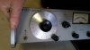
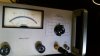
I wanted to give an update. I had a lot of fun hooking things up yesterday. I connected the AO-35 up to my variac through a Simpson 390 watt meter. On the signal side, I used a HP 651B Signal Generator (Sine Wave) to provide the signal and watched it on my Tek 422 scope. It worked!

That was the bulk of what we did. We tested the voltages around the tubes, and everything was basically to spec. I know that there is plenty to do on that front, but I wanted to get to the more important question, which is frequency response. I have two paths, I can either turn this into a guitar amp or a hi-fi amp. It seems that the hi-fi question can be answered by the frequency response of the circuit?

Given the equipment that I have, what is the best way to perform this test? Here is my understanding of what I do next. I set the Oscillator to 1 volt of output and 1 khz. I have an 8 ohm dummy resistor that will be hooked up to the speaker terminals. I connect my scope to the terminals.

From there, I take voltage readings from the speaker terminals at some increment from 20 hz to 30 khz.

Is this all I need to do to get the frequency response of the amp?

Youtube videos show some great sweep generators, I'm assuming that that isn't necessary.

Thanks!
 
How many watts are you looking for?...The power xmer run a pr. of 6v6's & a few preamp tubes. They're only good for 15 watts and they run hot, really hot. So it won't be a power house....
 
I'm a little confused about what to set my signal generators output at. The meter reads in either volts or db. Above, I assumed that I should set it to 1 volt...but is that correct?
 

Attachments

  • 20170213_074858.jpg
    20170213_074858.jpg
    44.2 KB · Views: 5
  • 20170213_074903.jpg
    20170213_074903.jpg
    40.9 KB · Views: 5
Adjust the sig generator output to get about 2.8 volts on the output, assuming you're working into an 8 ohm load. That will be 1 watt of output power. Check the frequency response there and see what you get.

Some of the frequency response will be controlled by the stuff at the front end, so you may need to remove the filters around the input to get reasonable numbers, or to at least figure out what the transformer is capable of.
 
Perfect. Thanks! It is an 8 ohm load. It was fun hooking this up. I'll be sure to post some pictures. And I'll get the results posted when I run the test.
 
By output, i mean output of the amp, not output of the generator, just to be clear.

A lot of amps will hit full output power by the 1 volt of input mark. Some are more or less sensitive than that but usually its a quarter volt either way.
 
Hook up a hi fi speaker and plug you iphone or whatever into the rca jack. Turn the volume to the lowest and turn everything on, curious as to what it would sound like before the circuitry gets modified. I never did that to mine, and the rca jack is long gone, so is most of the preamp filters. Crazy loud guitar amp with a 12 Celestion hooked up.
 
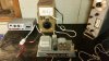
Here's a photo with everything hooked up. It is pretty darn exciting to make it come alive.

I may have done this incorrectly, but I calibrated the output level of the signal generator so that the voltage output from the amp was at 1.0 V at 1 kHz.

From there, I took readings at 20, 70, 120, 320, 680, 1000, 1.2k, 2k, 3k2, 8k1, 20k. Maybe this was too easy on the amp, but the readings were pretty flat until I hit 2 kHz. It dropped fairly sharply from there to 20k.

I did hook my phone up to it, turned the volume all the way down, and connected a good 6 ohm speaker. I don't have a good 8 ohm in my shop right now. There is a lot of background noise with this amp. I'd have to figure that out. It sounds okay. The highs were sort of harsh. I would want to spend some more time with it.
 

Attachments

  • 20170213_191242.jpg
    20170213_191242.jpg
    69.7 KB · Views: 20
  • 20170214_081456.jpg
    20170214_081456.jpg
    69.2 KB · Views: 19
That looks like low pass filtering. Did you feed the input in to the reverb input jack? If so, that does have some low pass stuff going on that you can easily pull to help that. To make a quick and dirty bypass, feed signal in at the point on the schematic where it says "Amplifier", the grid of the second 12AX7. That will give you just the power amplifier section without the front end and any filtering.
 
I was feeding right into the input jack. So it might be filtered. I set it up so that it feeds in at the grid of the second 12AX7.
 
You should go from input to volume pot 250k directly to the input tube grid. I've done a pr. for a friend and they sound very good. I think you'll be happy... Have fun.........
 
The input tube grid would be the first 12AX7? So the only change you made was adding a volume pot to each mono block?
 
To do this bypass, can I simply connect the signal generator output to the circuit right after C8?

That looks like low pass filtering. Did you feed the input in to the reverb input jack? If so, that does have some low pass stuff going on that you can easily pull to help that. To make a quick and dirty bypass, feed signal in at the point on the schematic where it says "Amplifier", the grid of the second 12AX7. That will give you just the power amplifier section without the front end and any filtering.
 
I think you will get a lot closer to the results you're looking for if you lift C4 out of circuit and apply input to the grid of V1B. Overall gain should be about right for hi-fi applications. C5 should be deleted as well, because it's surely rolling off the high end. In this way, you will be leaving feedback as designed around the power amp section.
 
Not overly familiar with NFB fed back in to the grid like this. Is R9 part of a voltage divider necessary for that to work correctly? Just thinking that a large resistor off the grid would also have a lot of roll off due to Miller effect concerns, though I guess you wouldn't really have much gain to worry about with the tube used like it is.

If its not needed, I might ditch R9 and C6 as well as C5. C5 is definitely adding some HF roll-off though.
 
Back
Top Bottom