• The move to the new server is done. There are some software and database maintenance updates in process. This has us passing the hat around to help out. We appreciate any donations. Seriously, even a dollar helps. The payment page may be found here - https://www.audiokarma.org/support.html

Harman Kardon 330A recapping

dlucy

dlucy67 (Doug)
Staff member
Moderator
Subscriber
Just to keep everyone guessing, I only replaced the electrolytic caps in this Harman Kardon 330A instead of replacing everything I could desolder. ;) For those of you who just want to do a minimal recap and you have the matching 330A, then this thread should help find the right parts to return your HK to sounding great and keep it playing for another 30 or 40 years.

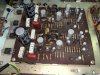
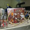
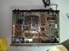
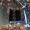
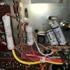
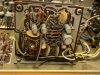
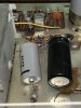
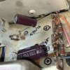
An important distinction: there are several variants of the HK 330A and this particular recapping only applies to one of those variants. If your 330A insides looks like these photos, then this recapping is for you:

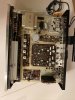
IMG_6154.JPEG IMG_6174.JPEG IMG_6182.JPEG IMG_6196.JPEG IMG_6199.JPEG IMG_6201.JPEG IMG_6204.JPEG

However, if your HK 330A looks like the following photos, instead, then this thread is not for you:

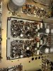
IMG_1693.JPEG IMG_1697.JPEG IMG_1716.JPEG

Another test to see if this recap is for your 330A or not is this: if your 330A has grey painted edges on the PCBs and grey painted trace lines on the PCBs, then you have a different 330A variant and this recap thread is not perfect for you.
 
Last edited:
Register to hide this ad
Cap selection

The following was used to select the caps for this recapping:
  • The schematic is wrong in at least one place and HK had several manufacturers build their 330As and there were more than one run, so all the values for the caps in this recapping BOM came right off the actual boards.
HK 330A Schematic vs actual vs replacement .jpg
  • All signal-bearing or audio path electrolytic caps over 1 uF were replaced with low leakage Nichicon KL series
  • All audio path electrolytic caps of 1 uF or lower were replaced with metalized film caps from WIMA MKS series
  • All power path electrolytic caps were replaced with high ripple current, low ESR caps Nichicon PW series, except...
  • The one power cap that was too big for the PW series, the 2200 uF 50 V power reservoir or "filter" cap was replaced with the cheapest Nichicon high ripple, low ESR snap in cap... and the lucky winner in the Doug-searches-Mouser's-in-stock contest this time was one from Nichicon KG series.
  • There are several caps that got an upgrade in the voltage department. For this particular recap, that was simply because Mouser carried a better (handles more voltage) cap for the same money or pennies more... and I buy in quantity so buying a higher-voltage cap will find application in more future projects... for the same money. Not important to anyone but me and a few equally-OCD AK'ers.
General notes

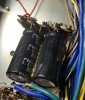
One of the caps on the schematic is listed as a 2200 uF 35 V single cap... but was implemented as two, side-by-side, glued-to-each-other 1000 uF 35 V caps. That made my neat spreadsheet with one column for quantity that is shared between "in the schematic" and "what I need to order" all messed up and I'm still mad about that. ;) correction courstesy of @painttoad

HK 330A one 2200 uf actually two 1000 uf caps.jpg
HK 330A one 2200 uf actually two glued 1000 uf caps.jpg

Some of the caps to be replaced are axial and it simply makes no sense to go to the extra expense of not-made-often-now axial caps and accept a lesser set of specs than the Nichicon PW series. So, the axials got replaced with Nichicon radials. And they don't look as cool. I'm OK with that.

IMG_6177.JPEG IMG_6228.JPEG

The PCB-mounted trimpots are open-frame design and made from phenolic or something similar that breaks and crumbles with age, a little Deoxit and any amount of pressure. So, they really, really need to be replaced, too. Especially if you plan to actually adjust the idle current and channel balance as per the manual. Replace these before doing any adjusting with the power on... you were warned.

HK 330A evil trimpots.jpg
 
Last edited:
HK 330A (original variant) recap only parts list

AM board
C205,C211 2 Capacitor Electrolytic 1 uF 50 V Signal 1 uF 63 V MKS 505-MKS2C041001F00MI
C206 1 Capacitor Electrolytic 33 uF 6.3 V Signal 33 uF 50 V KL 647-UKL1H330MPDANATD

Chassis topside
C913 (near transformer) 1 Capacitor Electrolytic 470 uF 16 V Axial 470 uF 25 V PW 647-UPW1E471MPD6
C915 (collared) 1 Capacitor Electrolytic 2200 uF 50 V 36mm 3300 uF 63 V KG 647-LKG1J332MESCBK
C918 ? (near transformer) 1 Capacitor Electrolytic 220 uF 25 V power 1500 uF 35 V PW 647-UPW1V152MHD1DU

Chassis underside
C914 (at location #47 and #48 on service manual photo) 2 Capacitor Electrolytic 2200 uF 35 V Power 1500 Uf 35 V PW 647-UPW1V152MHD1DU
C916 1 Capacitor Electrolytic 47 uF 35 V Axial 47 uF 50 V PW 647-UPW1H470MED
C917 1 Capacitor Electrolytic 220 uF 25 V Axial 220 uF 35 V PW 647-UPW1V221MPD1TD

FM board
C120 1 Capacitor Electrolytic 1 uF 50 V Signal 1 uF 63 V MKS 505-MKS2C041001F00MI

FM MPX board
C301,C303 2 Capacitor Electrolytic 1 uF 50 V Signal 1 uF 63 V MKS 505-MKS2C041001F00MI
C302 1 Capacitor Electrolytic 33 uF 6.3 V Signal 33 uF 50 V KL 647-UKL1H330MPDANATD
C311 1 Capacitor Electrolytic 10 uF 16 V Signal 10 uF 25 V KL 647-UKL1E100MDDANA

PHONO board (aka PREAMP, aka EQ board)
C401,C405,C409,C414 4 Capacitor Electrolytic 10 uF 16 V Signal 10 uF 25 V KL 647-UKL1E100MDDANA
C404,C413 2 Capacitor Electrolytic 33 uF 6.3 V Signal 33 uF 50 V KL 647-UKL1H330MPDANATD
C410 1 Capacitor Electrolytic 100 uF 16 V Power 100 uF 25 V PW 647-UPW1E101MED1TD

Combined preamp and power amp board (aka Predriver board)
C501,C502,C504,C506,C509,C510,C515,C516,C601,C602,C604,C606,C609,C610,C615,C616 16 Capacitor Electrolytic 1 uF 50 V Signal 1 uF 63 V MKS 505-MKS2C041001F00MI
C505,C605 2 Capacitor Electrolytic 100 uF 16 V Signal 100 uF 25 V KL 647-UKL1E101KPD1TA
C507,C607 2 Capacitor Electrolytic 10 uF 25 V Signal 10 uF 25 V KL 647-UKL1E100MDDANA
C508,C608 2 Capacitor Electrolytic 220 uF 6.3 V Signal 220 uF 16 V KL 647-UKL1C221MPD1TD
C513,C613 2 Capacitor Electrolytic 47 uF 50 V Signal 47 uF 50 V KL 647-UKL1H470MPDANA
C911,C912 2 Capacitor Electrolytic 1000 uF 35 V Signal 1000 uF 35 V KL 647-UKL1V102MHD​

BOM copy-and-paste-into-Mouser list

21 505-MKS2C041001F00MI
1 647-LKG1J332MESCBK
2 647-UKL1C221MPD1TD
7 647-UKL1E100MDDANA
2 647-UKL1E101KPD1TA
4 647-UKL1H330MPDANATD
2 647-UKL1H470MPDANA
2 647-UKL1V102MHD
1 647-UPW1E101MED1TD
1 647-UPW1E471MPD6
1 647-UPW1H470MED
3 647-UPW1V152MHD1DU
1 647-UPW1V221MPD1TD​
 
You are a valuable HK 330 resource here on AK.

Thank you for your detailed posts about these wonderful receivers!

IMO, very 'sticky-worthy' in a sub thread /forum somewhere here on AK.
 
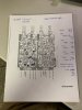
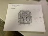
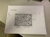
The foil or trace images of the boards in the service manual are mostly correct. I've indicated where the caps are and the positive lead on each:

IMG_6251.JPEG IMG_6252.JPEG IMG_6254.JPEG IMG_6255.JPEG IMG_6256.JPEG

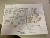
The power supply portion of the schematic isn't exactly perfect:

IMG_6253.JPEG
 
Hi Doug,

This is great. Thank you! Could you help me with the trim pots. I may have confused myself with an old tread you helped Spencer with a few years ago. Are these correct?

VR501, 601 300K 652-3362P-1-304LF (2)
VR502, 602 3K 5K 0.5 W 652-3309W-1-502 (2)

Thanks!
 
Screws, lamps, hardware and other non-electronics bits of a Harman Kardon 330A

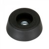
foot 260-7706 from Parts Express 260-7706_HR_0.default.jpg
Feet

  • The rubber or plastic feet on the bottom are 0.88" to 1.0" in diameter and 0.31" to 0.5" tall. I have had good success with Penn-Elcom 9120 Rubber Cabinet Foot 0.88" Dia. x 0.31" H part #260-7706 from Parts-Express.
  • The feet may be missing if your unit was installed in one of the OEM wood cabinets (as the feet came off and the feets' screw holes were used as attachment points by the underside of the wooden cabinet).
  • A #6 wood screw of at least 0.75" long is good for attaching the feet to the OEM holes on the bottom of the chassis.

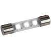
lamp 8V LED fuse style 070-121_HR_0.default.jpg
Tuning dial lamps

  • The tuning dial lamps are 8V AC fuse-type and can be replaced with just about any of the 8V LED conversion fuse-style LED assemblies. Not all of these fuse-style LED assemblies are the same! Some are lesser quality, some have slightly wider bodies. I have had good success with
    LED Fuse Lamp For Marantz Sansui Kenwood Yamaha Sony - Warm White 8 Volt 5 Pack part #070-121 from Parts-Express


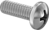
cap head screw 90272a540p1-b01-digitall@halfx_637060330140767082.png
Screws

  • The four screws on the sides that hold on the upper case cover are M4 wide truss head Phillips screws and need to be at least 8mm long. I've had good success with Metric 316 Stainless Steel Extra-Wide Truss Head Phillips Screws M4x0.7mm 10mm length part number 94792A118 from McMaster-Carr.
  • The nine screws on the bottom that hold the lower cover on are M4 cap or pan head Phillips screws. I've had good success with Metric 316 Stainless Steel Pan Head Phillips Screws M4x0.7mm 6mm length part number 92000A216 from McMaster-Carr.
  • The two smaller screws on the top of the upper case are M3x05.mm cap or pan head Phillips screws. I prefer the matching-black color of Metric Black-Oxide 18-8 Stainless Steel Pan Head Phillips Screws M3x0.5mm 5mm length part number 95836A203 from McMaster-Carr.
 
Hey Dlucy, do you know what size the smaller resistors are on the predriver board? I ordered 1 watt replacements, but they look a little small.... modern 2 watt resistors look a little big
 
Hey Dlucy, do you know what size the smaller resistors are on the predriver board? I ordered 1 watt replacements, but they look a little small.... modern 2 watt resistors look a little big
Manufacturers make the same watt resistors in different physical sizes for various reasons. Just because they look "smaller", doesn't mean a thing. If they are rated 1 watt, they are 1 watt. I have some 1/2 watt resistors that "look" like 1/8 watt.
 
Manufacturers make the same watt resistors in different physical sizes for various reasons. Just because they look "smaller", doesn't mean a thing. If they are rated 1 watt, they are 1 watt. I have some 1/2 watt resistors that "look" like 1/8 watt.

Ok the HK schematics don't list watt values on the resistors, any way to measure watts in a resistor? And would it be ok to use a replacement resistor of higher value? Say I use a 1k 5% 2watt resistor where a 1k 5% 1watt resistor was originally? Curious about that
 
Ok the HK schematics don't list watt values on the resistors, any way to measure watts in a resistor? And would it be ok to use a replacement resistor of higher value? Say I use a 1k 5% 2watt resistor where a 1k 5% 1watt resistor was originally? Curious about that

I don’t know of any way to measure the wattage of a resistor.

the HK gear uses 1/4 w resistors for most locations. Using a high wattage resistor is perfectly ok.
 
Ok the HK schematics don't list watt values on the resistors, any way to measure watts in a resistor? And would it be ok to use a replacement resistor of higher value? Say I use a 1k 5% 2watt resistor where a 1k 5% 1watt resistor was originally? Curious about that
All resistors are 1/4w unless noted. If one is a 1/2w, 1w, 2w, etc., it should be noted as such somewhere in the service manual.
 
@dlucy do you have any instructions on removing the faceplate for this version? I can’t seem to get mine off and it looks like it may need some work in tight spaces, but I’m not sure.
 
The PCB-mounted trimpots are open-frame design and made from phenolic or something similar that breaks and crumbles with age, a little Deoxit and any amount of pressure. So, they really, really need to be replaced, too. Especially if you plan to actually adjust the idle current and channel balance as per the manual. Replace these before doing any adjusting with the power on... you were warned.

View attachment 1886049
Did you have values and part numbers for the trimpots by chance?
 
If you give me the component numbers from the schematic, like "VR101", I can help you with finding replacement devices.
I am looking at the pre driver board so VR501, 502, 601, 602. Are those the only ones that would need any adjusting with new caps and transistors?
 
HK 330A (original variant) recap only parts list

AM board
C205,C211 2 Capacitor Electrolytic 1 uF 50 V Signal 1 uF 63 V MKS 505-MKS2C041001F00MI​
C206 1 Capacitor Electrolytic 33 uF 6.3 V Signal 33 uF 50 V KL 647-UKL1H330MPDANATD​
Chassis topside
C913 (near transformer) 1 Capacitor Electrolytic 470 uF 16 V Axial 470 uF 25 V PW 647-UPW1E471MPD6​
C915 (collared) 1 Capacitor Electrolytic 2200 uF 50 V 36mm 3300 uF 63 V KG 647-LKG1J332MESCBK​
C918 ? (near transformer) 1 Capacitor Electrolytic 220 uF 25 V power 1500 uF 35 V PW 647-UPW1V152MHD1DU​
Chassis underside
C914 (at location #47 and #48 on service manual photo) 2 Capacitor Electrolytic 2200 uF 35 V Power 1500 Uf 35 V PW 647-UPW1V152MHD1DU​
C916 1 Capacitor Electrolytic 47 uF 35 V Axial 47 uF 50 V PW 647-UPW1H470MED​
C917 1 Capacitor Electrolytic 220 uF 25 V Axial 220 uF 35 V PW 647-UPW1V221MPD1TD​
FM board
C120 1 Capacitor Electrolytic 1 uF 50 V Signal 1 uF 63 V MKS 505-MKS2C041001F00MI​
FM MPX board
C301,C303 2 Capacitor Electrolytic 1 uF 50 V Signal 1 uF 63 V MKS 505-MKS2C041001F00MI​
C302 1 Capacitor Electrolytic 33 uF 6.3 V Signal 33 uF 50 V KL 647-UKL1H330MPDANATD​
C311 1 Capacitor Electrolytic 10 uF 16 V Signal 10 uF 25 V KL 647-UKL1E100MDDANA​
PHONO board (aka PREAMP, aka EQ board)
C401,C405,C409,C414 4 Capacitor Electrolytic 10 uF 16 V Signal 10 uF 25 V KL 647-UKL1E100MDDANA​
C404,C413 2 Capacitor Electrolytic 33 uF 6.3 V Signal 33 uF 50 V KL 647-UKL1H330MPDANATD​
C410 1 Capacitor Electrolytic 100 uF 16 V Power 100 uF 25 V PW 647-UPW1E101MED1TD​
Combined preamp and power amp board (aka Predriver board)
C501,C502,C504,C506,C509,C510,C515,C516,C601,C602,C604,C606,C609,C610,C615,C616 16 Capacitor Electrolytic 1 uF 50 V Signal 1 uF 63 V MKS 505-MKS2C041001F00MI​
C505,C605 2 Capacitor Electrolytic 100 uF 16 V Signal 100 uF 25 V KL 647-UKL1E101KPD1TA​
C507,C607 2 Capacitor Electrolytic 10 uF 25 V Signal 10 uF 25 V KL 647-UKL1E100MDDANA​
C508,C608 2 Capacitor Electrolytic 220 uF 6.3 V Signal 220 uF 16 V KL 647-UKL1C221MPD1TD​
C513,C613 2 Capacitor Electrolytic 47 uF 50 V Signal 47 uF 50 V KL 647-UKL1H470MPDANA​
C911,C912 2 Capacitor Electrolytic 1000 uF 35 V Signal 1000 uF 35 V KL 647-UKL1V102MHD​

BOM copy-and-paste-into-Mouser list

21 505-MKS2C041001F00MI​
1 647-LKG1J332MESCBK​
2 647-UKL1C221MPD1TD​
7 647-UKL1E100MDDANA​
2 647-UKL1E101KPD1TA​
4 647-UKL1H330MPDANATD​
2 647-UKL1H470MPDANA​
2 647-UKL1V102MHD​
1 647-UPW1E101MED1TD​
1 647-UPW1E471MPD6​
1 647-UPW1H470MED​
3 647-UPW1V152MHD1DU​
1 647-UPW1V221MPD1TD​
These three items are no longer in production. Could you advise on Mouser alternatives:
647-LKG1J332MESCBK
647-UPW1E101MED1TD
647-UPW1H470MED

thank you
 
Back
Top Bottom