• The move to the new server is done. There are some software and database maintenance updates in process. This has us passing the hat around to help out. We appreciate any donations. Seriously, even a dollar helps. The payment page may be found here - https://www.audiokarma.org/support.html

Harman Kardon 330B (B-2) Restoration Thread - Information & Questions

puma1824

Member
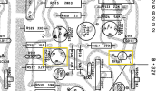
I'm in the process of recapping my 330B (B-2) and found that the schematic is wrong for some of the transistors. As a result I'm trying to determine what I can replace the transistor that has the labeling C1384 R 4B on it. I had planned on replacing the 2SC538A (C1509 R 3H) with a recommended KSC1845FTA. I'm confusing myself reading different threads related to transistors and now not sure if 2SC538A (C1509 R 3H) should be replaced with a KSC1845FTA and really not sure what to substitute for C1384 R 4B should be.

Any recommendations? I think they need to have a complimentary set? I think I can use a KSC1845 there as well...I think.
2025-08-23_22-47-37.png
 
Last edited:
Register to hide this ad
Does this seem accurate? If so it looks like I might be able to use a KSC1815 for both. Maybe @dlucy you may have some insight or knowledge? From past readings you appear to be the SME :). thanks

C1384 Replacements

These alternatives are also general-purpose NPN transistors with similar voltage and current ratings.
  • 2N3904: A very common, widely available NPN transistor.
  • BC547: Another popular general-purpose NPN BJT.
  • KSC1815: A direct cross-reference and an excellent replacement.

C1509 Replacements

These replacements are chosen for their higher voltage and current ratings, making them suitable for audio driver stages.
  • 2SC1815: A common replacement with similar electrical characteristics.
  • 2SC2240: A low-noise NPN transistor that is also a good fit for audio applications.
  • KSC1815: While also a replacement for the C1384, its ratings are close enough to be a suitable substitute in many C1509 circuits.
 
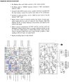
@puma1824 if you have a 330B B-2 series, you should not be using the 330A schematic. Instead, you should be using the "330B series B-2" schematic in the "Technical Manual Addendum"

1756131468500.png
 
Your first question: what is appropriate replacement in TR505 and TR605?

The 330B B-2 schematic & parts list has this as 2SC1384. I've seen a 2SC1509 in that position before.

The 2SC1384 is a pre-driver, a mid-power small signal transistor. It is rated for 1.5 A and 1 W in the TO-92 package. It's job is to amplify audio well, so not "general purpose". The replacements you are considering 2N3904, BC547, and KSC1815 are not a good choice for this location.

I've specified the KSC2690A in my prior 330B B-2 lists. That can be hard to find these days. You may be able to find the TTA004B useful as a replacement. Other AK'ers have used the MJE340, but maybe not in this position.
 
Your second question: what is the unmarked transistors you pointed out are TR504 and TR604.

The 330B B-2 calls for 2SC828 in those positions: low power, small signal, audio amplification in a TO-92 package. So, you'd want the lowest noise TO-92 you can put in there. The go-to for this is KSC1845F. It has a limitation of only handling 50mA, which would be bad to exceed, but I can tell you the 330B B-2 in this position will not exceed. So, KSC1845F is the right choice for the 2SC828 in this position.
 
@dlucy thanks so much! Complete newb moment not pivoting down to the supplemental section for the schematic.

Actually for the first question would be for TR507 & TR607. In the board diagram it's labelled as 2SC828 which I believe is incorrect based on what's installed in there currently. In TR508/608 is a 2SC38A which now I'm not sure what would be a good replacement for that either.

So for:
2SC828 (TR502/602/504/604) = KSC1845F and how about for previously not mentioned 2SC644 (TR501/601/503/603) I believe what is recommended would be a KSC1845F as well.

Would a KSC945F be better for either 2SC828 (TR502/602/504/604) or 2SC644 (TR501/601/503/603)?
 
So for:
2SC828 (TR502/602/504/604) = KSC1845F and how about for previously not mentioned 2SC644 (TR501/601/503/603) I believe what is recommended would be a KSC1845F as well.

Would a KSC945F be better for either 2SC828 (TR502/602/504/604) or 2SC644 (TR501/601/503/603)?

For this use, replacing 2SC828 and 2SC644 with KSC1845F is preferable. They have the right parameters and the lowest noise of any modern, available through hole TO-92 transistors with the same or reversible pinout.

2SC644 is sometimes used in radio frequency applications and, for those, KSC1845F would not be appropriate.
 
Thanks @dlucy Going to use KSC1845F for 2SC644(TR501/601/503/603) and 2SC828 (TR502/602/504/604). I originally installed a KSC945F in 2SC828 (TR502/602/504/604) but will swap them out.

Any recommendations for TR507 & TR607?

2025-08-25_21-27-32.png
 
Here are my transistor replacement recommendations for the HK 330B B-2 series:

Component number - Original models - replacement options
TR901-TR904 - 2SC789 - MJE15028, MJE15030, MJE15032, MJE15034​
TR508,TR608 - 2SA684, CDC9002 - KSA1220A, TTA004B​
TR507,TR607 - 2SC1384 - KSC2690A, TTC004B​
TR506,TR606 - 2SC1384, CDC8002 - KSC2690A, TTC004B​
TR505,TR605 - 2SC1509, 2SC1384 - KSA1220A, TTA004B​
TR501,TR503,TR601,TR603 - 2SC644 - KSC1845F, KSC945C
TR502,TR504,TR602,TR604 - 2SC828 - KSC1845F, KSC945C

@puma1824 you may want to wait for others to OK my list as I pulled it together quickly and it would help to be double checked before ordering.
 
Here are my transistor replacement recommendations for the HK 330B B-2 series:

Component number - Original models - replacement options
TR901-TR904 - 2SC789 - MJE15028, MJE15030, MJE15032, MJE15034​
TR508,TR608 - 2SA684, CDC9002 - KSA1220A, TTA004B​
TR507,TR607 - 2SC1384 - KSC2690A, TTC004B​
TR506,TR606 - 2SC1384, CDC8002 - KSC2690A, TTC004B​
TR505,TR605 - 2SC1509, 2SC1384 - KSA1220A, TTA004B​
TR501,TR503,TR601,TR603 - 2SC644 - KSC1845F, KSC945C
TR502,TR504,TR602,TR604 - 2SC828 - KSC1845F, KSC945C

@puma1824 you may want to wait for others to OK my list as I pulled it together quickly and it would help to be double checked before ordering.

Thanks again! I have no idea how you can keep up with all cross-references. I need to create some sort of database or spreadsheet that can be queried or filtered lol.
 
Thanks again! I have no idea how you can keep up with all cross-references. I need to create some sort of database or spreadsheet that can be queried or filtered lol.
My database is the search link in the upper right corner.
 
Thanks again! I have no idea how you can keep up with all cross-references. I need to create some sort of database or spreadsheet that can be queried or filtered lol.

I keep a spreadsheet on each of the restores I do. For these questions, I just went back to the 330B B-2 spreadsheets I’d made at those times. They are the results of research, threads here in AK and the actual results of those restores.
 
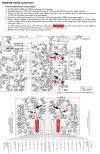
First off, I am new to vintage audio repair and using oscilloscopes. I've just finished recapping one side of the Predriver board of my Harman Kardon 330B (B-2) and wanted to try adjusting the predriver.

I don't know why I'm having so much difficulty understanding adjustment procedures written in the tech manuals. IF I read this correctly are my translated procedure seem correct? Are there test points on the board I should connect the oscilloscope to instead of to the speaker terminals?

Receiver Setup
  1. Set Balance, Bass, and Treble controls to their center position.
  2. Set the Mode Switch to "STEREO", the Speaker Switches to "ON", and the Selector Switch to "AUX".
  3. Connect a speaker load by attaching an 8 ohm (50W) resistor to pos (+) and GND (-) of the <LEFT or RIGHT> speaker terminals
Oscilloscope & Audio Generator Setup
  1. Connect the oscilloscope to pos (+) and neg (-) to the <LEFT or RIGHT> speaker terminals
  2. Connect an audio generator to the "AUX" <LEFT or RIGHT> input and set it to produce a 1,000 Hz (sine wave)

<LEFT or RIGHT> Channel Adjustment

  1. Rotate receiver volume control to full volume (clockwise)
  2. Adjust the audio generator's volume until the sine wave on the oscilloscope just begins to clip.
  3. Adjust DC balance VR 501 to make the positive and negative halves of the sine wave equal and symmetrical, removing the clipping.
  4. Adjust crossover potentiometer VR 502 until the crossover notch disappears by either:
    - Rotating receiver volume counter clockwise to get 0.1 watt (0.9 V RMS) output
    OR
    - Using a DC mV meter - adjust idling current connected to R918 (0.5 ohm) to 10mV

330B-2 Predriver Adjustment.jpg
 
Last edited:
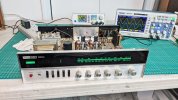
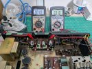
It can be a bit of a head scratcher interpreting the service manual but after hooking up 8 ohm 50 watt resistors to the speaker terminals, I turn it on and let it sit for 15 - 20 minutes to allow everything to warm up and settle down. Then the signal generator gets hooked up to AUX with a 1000 Hz 0.5 volt sine wave setting followed by the scope hooked across the same speaker terminals as the resistors are hooked up to.

Since I don't know how or if I can adjust the power output on my generator, I have the volume control on the receiver turned right down and slowly turn it up until I see clipping on the scope. Then the required VR gets adjusted to equalize the clipping on both the positive and negative waves. I don't keep the volume knob turned up too long as the resistors do get hot.HK 330A On THe Scope.jpg

To adjust the idle, or bias current, I like to use two DVM's instead of the scope and hook them both up to the indicated emitter resistors and adjust the VR's so I can read both channels at the same time. I don't think the B2 has test pins for this purpose so you'll have to clip straight to the indicated emitter resistor. Mini grabbers come in handy here. (630 Twin shown on dim bulb before being switched to full line power)
HK 630 Idle Bias Setting.jpg
Resistors used.
8 Ohm 50 W Resistors.jpg
 
It can be a bit of a head scratcher interpreting the service manual but after hooking up 8 ohm 50 watt resistors to the speaker terminals, I turn it on and let it sit for 15 - 20 minutes to allow everything to warm up and settle down. Then the signal generator gets hooked up to AUX with a 1000 Hz 0.5 volt sine wave setting followed by the scope hooked across the same speaker terminals as the resistors are hooked up to.

Since I don't know how or if I can adjust the power output on my generator, I have the volume control on the receiver turned right down and slowly turn it up until I see clipping on the scope. Then the required VR gets adjusted to equalize the clipping on both the positive and negative waves. I don't keep the volume knob turned up too long as the resistors do get hot.View attachment 3585115

To adjust the idle, or bias current, I like to use two DVM's instead of the scope and hook them both up to the indicated emitter resistors and adjust the VR's so I can read both channels at the same time. I don't think the B2 has test pins for this purpose so you'll have to clip straight to the indicated emitter resistor. Mini grabbers come in handy here. (630 Twin shown on dim bulb before being switched to full line power)
View attachment 3585116
Resistors used.
View attachment 3585123
Thanks! Super helpful again. Saw you have the 630 hooked up. I think if I read this correctly you can alternatively use TP1/TP2 (Left) & TP3/TP4 (Right) for the DVM

2025-08-31_08-59-20.png
 
Last edited:
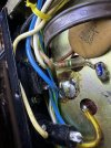
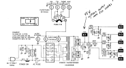
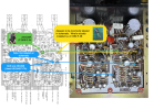
I'm currently in the process of refurbishing a Harman Kardon 330B (B-2) receiver and notice this solder blob on the bottom located near the power cord & accessory power plug. Not sure if a previous owner removed something. Anyone know what was possibly here and how it's hooked up? Here's the schematic for around that area below. Anyone have a pic of theirs?

IMG_1600.jpeg
2025-08-31_17-36-08.png
 
Back
Top Bottom