• The move to the new server is done. There are some software and database maintenance updates in process. This has us passing the hat around to help out. We appreciate any donations. Seriously, even a dollar helps. The payment page may be found here - https://www.audiokarma.org/support.html

Harman Kardon 430 - Left Channel Noise

JB8

Well-Known Member
Squad,

I have a 430 presenting very low level noise at start up on left channel only, right channel is silent. Noise sounds like a freshly poured Dr. Pepper fizzing down, not loud, not pop corny, just steady noise. Assumed issue was power supply as its present at no volume and across all functions. Can be heard through headphones and via speaker as well.

Having dealt with similar issues before (via your generous Audiokarma coaching) I tracked down the "bad" transistors from the infamous list, replaced the 458's and 1345's on the main amp with no change. Checked voltages on the remaining transistors (2SA77's, 2SC1509's) and they were similar across both channels and matched specs so I'm assuming they're not the culprits, but I could be wrong. Idle for both channels was in the 12 mV range at start up.

Then I started thinking it was cap related, so I replaced all power supply and main amp caps with like values with the exception of the main filter caps. I have the main caps and can install them but would appreciate some guidance on what else to check before doing so.

Thanks in advance for any advice you can offer!

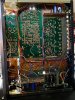
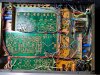
IMG_9904.jpg IMG_9905.jpg
 
Last edited:
Register to hide this ad
The 430 is, apart from the power supply, the same as the 330c… so threads here on AK about the 330c will mostly apply to your 430, too.

The main power reservoir caps are very unlikely to cause consistent audible noise in the output. Not impossible; just unlikely.

it sounds like a transistor problem… so you could, one by one, swap the left channel audio path transistors for the same in the right channel… and see if the noise swaps channels.
 
Thank you, Doug! Getting a response from you is like getting a response from Enzo based on sending a general inquiry to Ferrari. You're a legend and I'll gladly take your advice on the transistor swapping technique.

If I do end up just replacing the remaining transistors, across both channels, I'll reference some of your past 330c and 430 threads to determine modern alternatives. I appreciate the reminder that these two units are pretty tight siblings with lots of like components.

Thanks again, I'll let you know how it goes!
 
Thanks for the kind words, @JB8 , but keep in mind I’m just a regular ol’ AK’er… and therefore wrong plenty of the time…. ;)
 
  • Like
Reactions: JB8
Quick update, I replaced the rest of the transistors on the left channel. Figured if I was doing the swapping I'd just as soon replace them since I'd already replaced all the caps and other transistors - for some reason I can't get it through my thick skull to just track down the single culprit instead of replacing a bunch of components hoping it will be the remedy.... Man, so frustrating. There's time, I can still learn, I'll pump the brakes with some force on the next project that requires this kind of troubleshooting. Btw, when I was replacing the transistors on the left channel I did them one at a time, double checked the pinout every time and would test in between each replacement to listen for changes.

Since the noise persisted I decided to change out the main filter caps (only left channel so far), still no change. For all of the caps I replaced I used like values, for the transistors I've used 1845's for the 458's and 1345's, the 2SA777's were replaced with KSA1220A's, the 2SC1509's replaced with KSC2690's.

At this stage I'm stumped. I know other's have said sometimes you just need to live with the noise, but I just can't, especially since it's significantly louder on one channel. The right channel, although it was described as silent, still does have a very minimal, acceptable noise floor.

Any ideas? I'm up to my neck in this thing, would love to push it over the hump and justify all the new components, ha!

Thanks again for any advice you can offer, much appreciated.

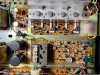
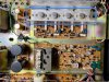
IMG_9945.jpg IMG_9946.jpg
 
Last edited:
Also, the main output transistors (2SC1030's) all tested fine as well. I'm assuming the transistors on rectifiers A and B are likely not involved since they're not channel-specific? Would really love to get this thing wrapped up, but the left channel is still whispering "shhhhhhhhhh".....

Thanks again for any help, I'm ready to learn and I'm not going to replace any other components until I have some guidance, ha!
 
When you say “the output transistors tested fine”, what kind of test did you mean?

you could eliminate them as the source of the problem by swapping the output transistors in the left channel for those in the right… if the noise followed, then you know what components are bad… if not, you know which components are _not_ the problem
 
Do you have an oscilloscope? If so, you can use it to find where the noise first originates in the signal and eliminate everything in the path prior to that point.
 
Thank you, @dlucy, I was referring to Q417-420, shown in the blue rectangle. I tested them in-chassis but can swap to see if one or more are the culprits.

IMG_9946.jpg

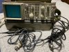
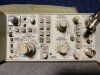
Thanks for hopping in, @nicholas2381, I actually picked up my first oscilloscope (Leader 325) a couple months back but haven't used it yet. I plugged it in and tried to essentially normalize the settings based on some paperwork I found for a similar Leader unit, and it appears to be working but I'd love to actually hook it up and officially get it in the mix.

Is there a simple way for me to hook it up to start testing the origin of the noise? I hate to ask for complex directions and appreciate your time, so if you can get me heading in the right direction I'm game to start probing! It came with several leads/probes, etc. Honestly I've been waiting for the right time to get my feet wet with this thing, perhaps now it the time!

IMG_9948.jpg
 
Thank you, @dlucy, I was referring to Q417-420, shown in the blue rectangle. I tested them in-chassis but can swap to see if one or more are the culprits.

View attachment 2424134

Thanks for hopping in, @nicholas2381, I actually picked up my first oscilloscope (Leader 325) a couple months back but haven't used it yet. I plugged it in and tried to essentially normalize the settings based on some paperwork I found for a similar Leader unit, and it appears to be working but I'd love to actually hook it up and officially get it in the mix.

Is there a simple way for me to hook it up to start testing the origin of the noise? I hate to ask for complex directions and appreciate your time, so if you can get me heading in the right direction I'm game to start probing! It came with several leads/probes, etc. Honestly I've been waiting for the right time to get my feet wet with this thing, perhaps now it the time!

View attachment 2424153

Are you comfortable reading the schematic for the unit? If so, I'd start at the amplifier output board - attach your probes to the signal input on signal input pin for R & L (ground clip to the chassis) and see if the signal looks identical. If it does, the problem is after the signal input to the board. You can verify that it's on the board by locating the signal output pins on the board and doing the same. If the signal is good in and bad out, you've narrowed the issue to that board. If it's bad coming into that board, then it's earlier in the signal path.

Just be sure you're comfortable with the oscilloscope. Like everything in this hobby, you're dealing with electricity. Follow good safety practices, don't short things by wildly probing, etc.
 
Thank you, @nicholas2381, this all makes sense. I'm comfortable with the schematic and will heed your warning around safety (no wild probing). I've been dabbling in the hobby for around a year now, mainly replacing bad transistors and caps so this jump to using the scope was bound to happen at some point.

Ok, in all transparency, this is usually the point in the conversation where I would say, "Check, got it, I'm good and can figure out some of the next steps". Well I'm turning the page and instead have a few more questions just so I can get more of the process correct from the outset...

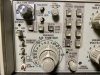
For the two channel leads on the scope, I see I can choose AC, Ground, or DC, so I assume I should choose DC for the channel 1 probe, then attach the channel 1 probe to the IN or OUT on the main amp board I'm testing, then have the channel 2 lead on Ground and attached to the chassis, as you noted. Is this accurate? Also, are there any settings or buttons I'll need to address on the scope so it gives me the read out I'm looking for? Do I need to run a test tone through the unit when I'm testing or just turn it on and start testing? Is there a function setting on the receiver I should adjust to or does it matter?

Thanks again for the assist, big step here for me but it will pay big dividends if I can learn the steps properly.

IMG_9949.jpg IMG_9950.jpg
 
You’ll want to select AC on both probes. Your probe should have a ground clip that you should attach to the chassis.

The positive part of the probe should connect to in or out (same on each channel).

You will need a test tone/signal. Attach it to the aux (or similar) input.
 
Excellent, I think this should get me going, I'll let you know how it goes, thanks again!
 
One last question for now, should I be checking both channels simultaneously? For example, both probes on both IN's, with the ground clip for each probe connected to chassis? Pretty sure that's what you were prompting, just want to double check. And a 1K test tone? I have a signal generator app so I can just run that straight into the Aux RCA's.

IMG_9951.jpg
 
Yes - that’s the easiest way. Then you can either put both channels on the screen at once or easily swap between them to check for difference. Knowing that the right channel sounds fine that’s your baseline. Just make sure the settings are identical on the two channels.

1K should be fine for the frequency.
 
  • Like
Reactions: JB8
Well that was fun but I don't think it was conclusive.

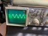
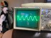
When I first hooked it all up (testing the IN's first) I was encouraged when channel 1 looked like this:
IMG_1943.jpg
And channel 2 looked like this:
IMG_1944.jpg

I then realized channel two was indeed hooked up to the right channel, the good channel, so I think maybe this scope, or at least channel 2, is bad. I then tested both the IN's and OUT's using the good test lead. Both channels on the IN's looked like my first pic above, the OUT's looked similar but presented a phantom second sine wave that would pop in and out:
IMG_1947.jpg

My assumption is that the IN signal is fine across both channels since the wave was so steady but there's something on the main amp section that's still out of whack because the OUT wave was not as steady? I've replaced all of the transistors on the left channel with the exception of Q418 & 420 but I'm hesitant to replace them since the voltages looked fine across all of the 2SC1030's.

A bit stumped now, open to suggestions.
 
This is good progress. You have narrowed it down to that board.

Signal seems out of phase. Have you done the biasing and DC order procedures in the service manual?
 
Yes, calibrated to ~24 mV across both channels so the idle seems good but maybe I'm missing something? Actually, just looked at the schematic again and I definitely did it wrong - did not attach an 8 ohm resistor across the speaker outs, did not set in Aux function, so I likely need to do it again. Will need to see if I have that specific resistor in my box of components. I essentially just let the unit warm up and checked mV's across the test points.

Do you think the signal being out of phase could cause such a significant difference between the channels specific to the "shhhhhh" sound I'm hearing? The right channel still has a bit of that in the background but the left is much much louder via both speaker options and headphones.
 
The 8 ohm is resistor is a dummy speaker load. Looks to the amp as if you have an 8 ohm speaker connected.

Im not entirely sure if it’s the cause or a symptom. You can use your scope to check points in the signal path and see where the problem first occurs. You know it’s fine entering the board, so move to the next point in the path.

When you find it, you’ll likely have your culprit.
 
Back
Top Bottom