• The move to the new server is done. There are some software and database maintenance updates in process. This has us passing the hat around to help out. We appreciate any donations. Seriously, even a dollar helps. The payment page may be found here - https://www.audiokarma.org/support.html

Harman Kardon 630 - ac fuse disconnected

kirbjas

AK Subscriber
Subscriber
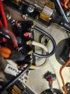
Checking out a harman kardon 630 and looks like some interesting wiring changes have been made. The connections to the ac fuse have been cut and 3 fuses have been mounted on the chassis. One of them may be a slow fuse. The power supply pcb is missing a cap and diode (assuming sm is correct) and the blue and red wires from both transformers are not connected. Some pics attached. Reviewing the schematic and other posts yet but not sure yet what to make of this.

 

Attachments

  • 20260207_141149.jpg
    20260207_141149.jpg
    131.2 KB · Views: 12
  • 20260207_141136.jpg
    20260207_141136.jpg
    125.4 KB · Views: 12
  • 20260207_140554.jpg
    20260207_140554.jpg
    171.5 KB · Views: 10
  • 20260207_140548.jpg
    20260207_140548.jpg
    157.2 KB · Views: 11
  • 20260207_140536.jpg
    20260207_140536.jpg
    201.9 KB · Views: 11
  • 20260207_140508.jpg
    20260207_140508.jpg
    120.3 KB · Views: 12
Register to hide this ad
voltages are sort of close to what they should be:
29v/-29v for all 4 supplies to predriver board (bit lower than 32v but close)
22v to preamp but does take about 20s to reach that level after turning on
I've been running it on a 100w dim bulb and it does work mostly but sometimes it does light up and the dial lights go dark (once when I tried turning bass adjustment all the way up, sometimes when engaging the speakers)
filter caps are measuring low (a couple in the 2000 uf range and the other 2 in the low 4000s, should be 4700 uf)
 
Looks like there is a voltage selector switch, set to 117v. Not sure that explains the cut wires to it or the fuse changes. Does anyone know how this switch is supposed to be wired? There is nothing about it in the sm. The terminals that have the red and blue cut wires are loose as is the one with white wires that are still connected.
 

Attachments

  • 20260207_170141.jpg
    20260207_170141.jpg
    134.8 KB · Views: 9
  • 20260207_165905.jpg
    20260207_165905.jpg
    152.2 KB · Views: 9
One mystery solved at least, the missing cap and diode on the power supply tuner preamp board seem to be related to service bulletin 165. It doesn't look like they did exactly what the bulletin says but I think it works out to the same thing. Bulletin says to connect + terminal of c904 to the collector of TR-801 but instead the + terminal of c904 is connected to the + terminal of c906). The + terminal of c906 is connected to the collector of TR801 and TR802, so I think this works out ok (circled areas of schematic that are relevant).
 

Attachments

  • hk630 ps.png
    hk630 ps.png
    69.6 KB · Views: 1
Still not sure why the fuses were installed the way they were but will move on to replacing the capacitors that are out of spec. Found a great thread for that:
 
Back
Top Bottom