• The move to the new server is done. There are some software and database maintenance updates in process. This has us passing the hat around to help out. We appreciate any donations. Seriously, even a dollar helps. The payment page may be found here - https://www.audiokarma.org/support.html

Harman Kardon 630 Twin Powered - blazing a trail

hopjohn

Silver Face
Subscriber
In comparison to other H/Ks of the era, information on repairing a 630 is pretty lacking. I'm concluding that these just aren't all that common. I bought one with the intention of restoring it fully in hopes it might sound similar to a Marantz 2238 I recently finished for someone. That really didn't turn out to be the case, each sounding uniquely their own.

The Service Manual for the 630 has frequent errors, and numerous differences in parts from stock components that I found in my untouched unit. The PCBs are free of any silk-screening on the component side of the boards, just blank. The PCB's solder side has a few markings to designate some board to board wiring, but that's really about it. So you're left at the mercy of potential replacement errors without a plethora of photographs to guide you.

I intended to do some documenting here, to help uncover some things for those in the future who might try to do a restoration for themselves, but I feel like the amount of effort required to provide thoroughly useful information would prove lacking for a number of reasons.

Firstly, as I got into my own unit I found that two of the shielded IF transformers were broken internally allowing the top slug to move freely up and down. So without buying a replacement board I'm not sure I'd ever be able to sort that out. Secondly, its not uncommon for the unobtainable MPX IC in these to go bad, which would only be determined once I got the IF section working. Thirdly, I have other tuners in my collection that far surpass the capabilities of the FM section in the 630 anyway, so it seemed rather pointless for me to bother with a restoration in these areas for a piece intended for my own collection.

Knowing that this was going to be an incomplete restoration I opted not to do the phono EQ board as well. I rarely listen to LPs, but when I do I typically prefer to use my Kenwood KA-9100. My primary objective at this point was to make the power supplies, tone amp, and power amp the area of focus. As I said before my main motivation was seeing how this stacked up against a Marantz 2238 and introducing myself to the H/K Contour circuit that seems well appreciated.

That said, I'll be posting some information in the coming days to act as a starting point at the very least since there is so little about this model out there.
 
Register to hide this ad
Bummer about those IF cans being busted. It's possible someone messed with them due to an FM problem so you may be bypassing some trouble. I've worked on a couple H/K's but never a 630 so it will be interesting to watch and I'm glad you'll be recording some useful info. :thumbsup:
 
Awesome! Thank you for sharing on this one.

Secondly, its not uncommon for the unobtainable MPX IC in these to go bad, which would only be determined once I got the IF section working.

Which model / part number is it? Just curious....
 
Which model / part number is it? Just curious....
According to the manual its a MC1301, but it's one of most errant SM I've come across. The photo reveals it to be a Sylvania ECG-722 7436

fB30icX.jpg
 
According to the manual its a MC1301, but it's one of most errant SM I've come across. The photo reveals it to be a Sylvania ECG-722 7436

EDITED: A quick (and not double-checked) Google search suggests ECG722 = NTE722 = LM1307. A quick check of the pinouts on NTE722 to LM1307 looks like they are the same. So ECG722 might actually be replaceable with more-obtainable LM1307.
 

Attachments

Last edited:
Overview
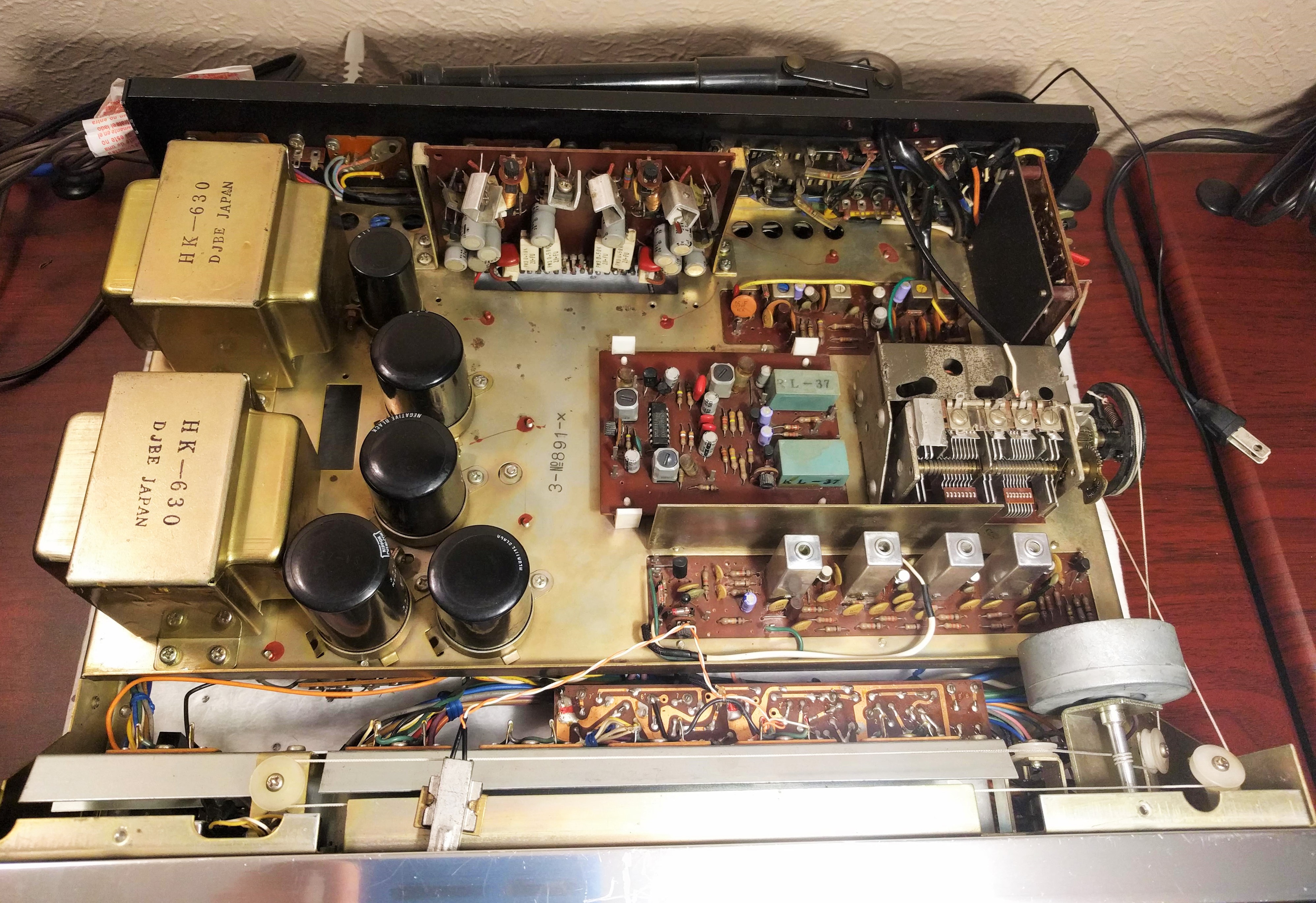
These full chassis view photos provide a lay of the land top and bottom.
aFPc08zk_o.jpg

Top Chassis View

6PXvXrFu_o.jpg

Bottom Chassis View

I'll just be presenting the boards that I actually performed work on. Again, I ignored anything to do specifically with AM/FM and phono sections so know that this is not a comprehensive thread. I encourage others to build on what I post here. The errors in the service manual that I detail are limited in scope to the components I replaced. I do not rule out the possibility for further errors to exist outside these areas of focus. Remain diligent.

Tone Amp Board


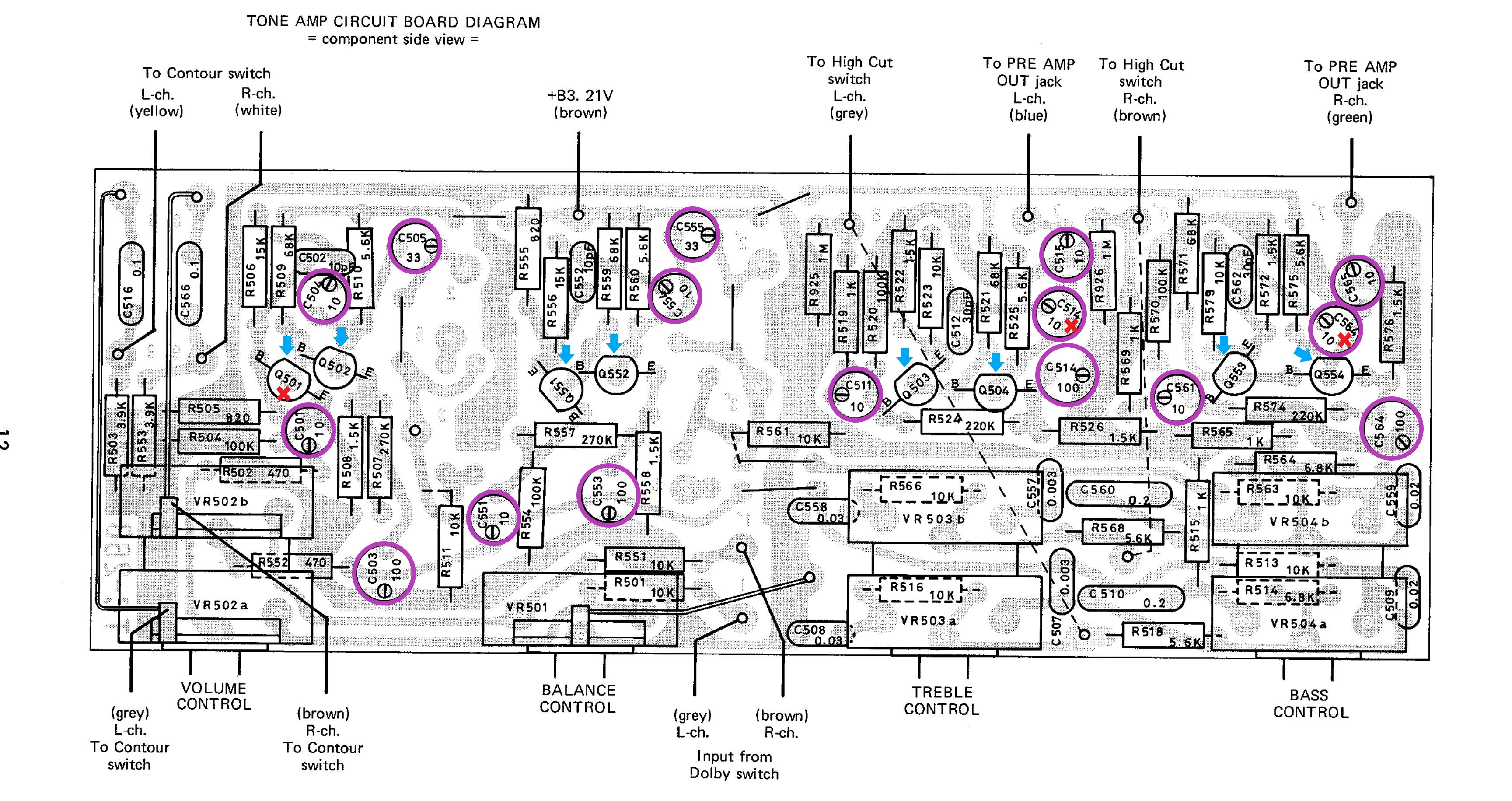
I'll begin with the Tone Amp board. The board diagram below shows the component side view with the controls pointing downward.
  • A red X - denotes an error of some kind that I detail below
  • The pink circles denote electrolytic capacitor locations
  • The blue arrows indicate transistor locations
eokRJ7MU_o.jpg

H/K 630 Tone Amp Board Diagram

Errors:
C513 & C563 - The board diagram errantly uses both ID# C514 and C564 twice. These are correctly identified as 100uf caps, but also incorrectly identified as 10uf caps. The 10uf caps marked with the red X should be ID# C513 & C563 respectively.

Q501 - is shown in the board diagram rotated 180 degrees the wrong way round. The flat side of the transistor should face bottom left with the emitter adjoining R506 and the base adjoining the positive terminal of C501.


Tone Amp
The actual voltage values of the stock capacitors differed slightly in some cases from what is shown on the schematic. I've listed the values below that were actually pulled from my unit. Also note that the board diagram doesn't provide capacitors voltages at all, showing just the capacitance value. The capacitors I used for replacement on the tone board are all Nichicon UKL series, but you are certainly free to go with your preference. I took a very basic approach to the recapping here. I'd recommend going with stacked film caps at the input and outputs locations C501, C551, C515, C565 if you think you can squeeze them in. I verified that all of the electrolytic capacitor polarities shown on the tone board diagram to be accurate. Note that the polarity markings shown on the diagram are for the negative (-) terminal.
C504 10uf 16V >> 10uf 50V KL
C501 10uf 16V >> 10uf 50V KL
C505 33uf 25V >> 33uf 50V KL 8mm
C503 100uf 6.3V >> 100uf 25V KL 8mm
C551 10uf 16V >> 10uf 50V KL
C553 100uf 6.3V >> 100uf 25V KL 8mm
C555 33uf 25V >> 33uf 50V KL 8mm
C554 10uf 16V >> 10uf 50V KL
C511 10uf 16V >> 10uf 50V KL
C515 10uf 16V >> 10uf 50V KL
C513 10uf 16V >> 10uf 50V KL
C514 100uf 6.3 >> 100uf 25V KL 8mm
C561 10uf 16V >> 10uf 50V KL
C565 10uf 16V >> 10uf 50V KL
C563 10uf 16V >> 10uf 50V KL
C564 100uf 6.3V >> 100uf 25V KL 8mm

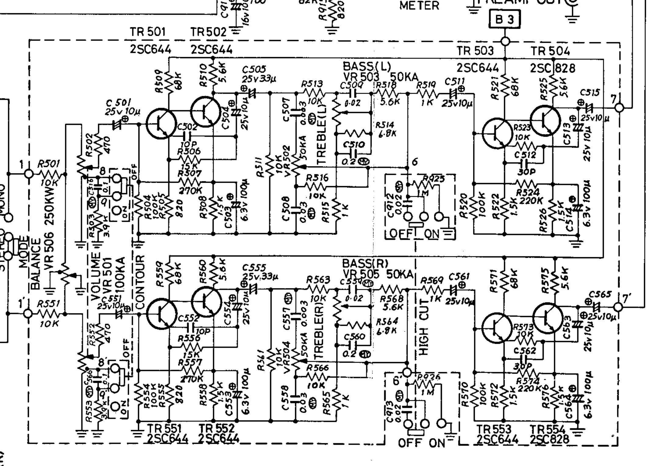
The transistors found in my unit were the following, and exactly matched those shown on the schematic. For whatever reason H/K decided to mark the schematic with TR# identifiers rather than remain consistent with the Q# identifier of the board diagrams.
Q501-503 2SC644 ECB >> KSC1845F ECB
Q551-553 2SC644 ECB >> KSC1845F ECB
Q504/Q554 2SC828 ECB >> KSC1845F ECB

19M3rFNv_o.jpg

H/K 630 Tone Amp Board Schematic

PlTCVDT2_o.jpg

H/K 630 Tone Amp Board in stock form.
 
Last edited:
Work in progress...

Power Supply

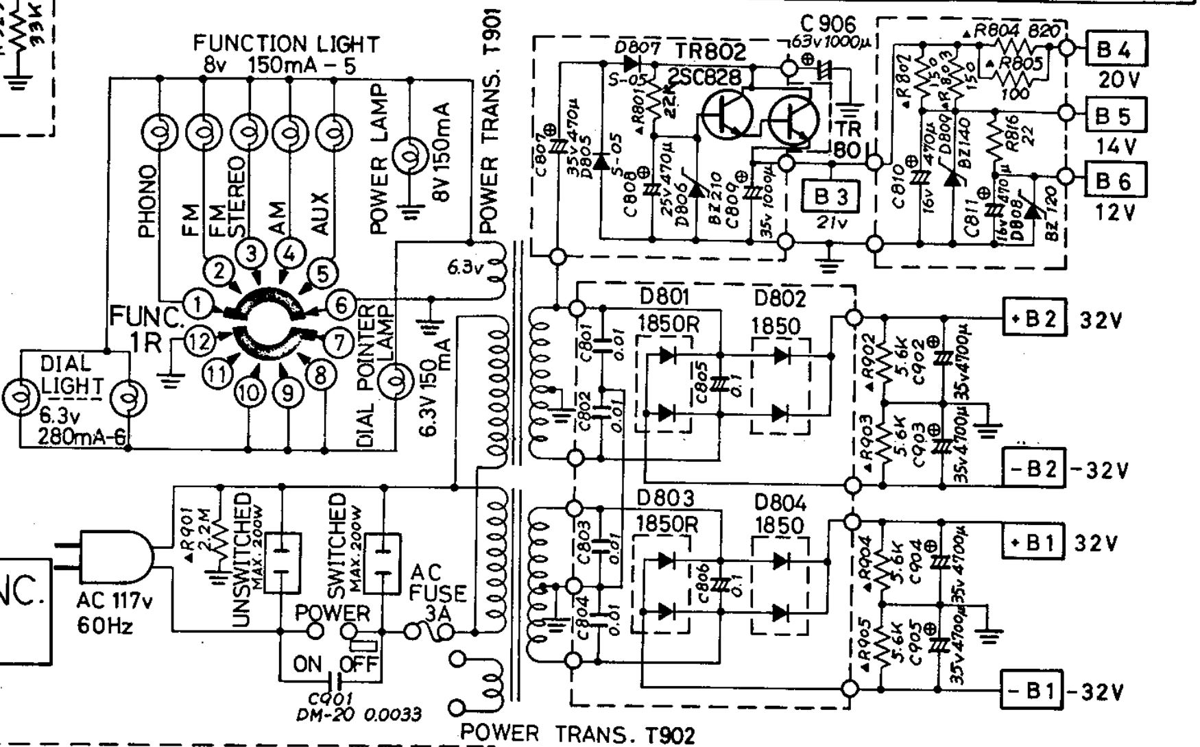
The H/K 630 has two power transformers, three small boards, and five chassis mounted filter capacitors that make up the power supply. The three small boards are identified as "Power Supply Circuit Board", "Power Supply (Tuner and Preamp)", and "Regulator Circuit Board". According to the service manual the "Power Supply (Tuner and Preamp)" comes in two versions. My unit included version 2 so that is the one I'll be discussing.

qDmMURJj_o.jpg

H/K 630 Power Supply Schematic

H/K 630 Power Supply Circuit Board (Board 1 of 3)
PUfaiVY9_o.jpg

H/K 630 Power Supply Circuit Board Diagram

kXZApC4Y_o.jpg

H/K 630 Power Supply Circuit Board Diagram in stock form

Power Supply Circuit Board Parts List
C805/806 0.1uf 400V Oil caps >> 0.1uf 400V Polyester Film
D801/803 1S1850R rectifier |<- ->| dual, common anode >> MUR1620CTRG 200V, 8A per leg
D802/804 1S1850 rectifier ->||<- dual, common cathode >> MUR1620CTG 200V, 8A per leg

H/K 630 Power Supply (Tuner and Preamp) Version 2 (Board 2 of 3)
MXuQguLB_o.jpg

H/K 630 Power Supply (Tuner and Preamp) Version 2 Diagram

1lGhsdYW_o.jpg

H/K 630 Power Supply (Tuner and Preamp) Version 2 in stock form

Error: TR802 - The pinout shown in the board diagram for TR802 is flipped 180 degrees. The front of TR802 should face the capacitors. The emitter should be on the left side closest C808 and base on the right side closest to C807.

Power Supply (Tuner & Preamp) Version 2 Parts List
TR801 is heatsink mounted with a live collector tab and needs to be insulated. Be sure to save the original insulating washer that is specificlaly designed to fit the heatsink when installing a replacement. The board diagram doesn't show the capacitor values for C807 and C808, but they are correct as provided below.
C807 470uf 35V 16mm >> 560uf 50V UPJ 16mm
C808 470uf 25V 16mm >> 560uf 50V UPJ 16mm
TR801 2SD234 TO-220 BCE >> TIP41C TO-220 BCE
TR802 2SC828 TO-126 (2SC495 pulled ) ECB >> KSC2690 TO-126 ECB
D805/807 S-05 >> Didnt change...possible sub 1N4007
D806 BZ-210 (21V 1W) >> 1N4740A (10V 1W Zener) & 1N4741A (11V 1W Zener) in series
R801 22K 1/2W Carbon Comp >> 22K 1/2W metal film

H/K 630 Regulator Circuit Board (Board 3 of 3)
8JkShnw3_o.jpg

H/K 630 Regulator Circuit Board Diagram

wi6gyEK5_o.jpg

H/K 630 Regulator Circuit Board Diagram in stock form

H/K 630 Regulator Circuit Board Parts List
C809 1000uf 35V 18mm >> 1200uf 63V UHE 18mm
C810 470uf 16V 12.5mm >> 680uf 50V UPS 12.5mm
C811 470uf 16V 12.5mm >> 680uf 50V UPS 12.5mm
R802/803 150 Ohm 1/2W Carbon Comp. >> 150 Ohm 1/2W Metal Film
R804 820 Ohm 1/2W Carbon Comp. >> 820 Ohm 1/2W Metal Film
R805 100 Ohm 1/2W Carbon Comp. >> 100 Ohm 1/2W Metal Film
R816 22 Ohm 1/2W Carbon Comp. >> 22 Ohm 1/2W Metal Film
D808 >> BZ120 12V 1W Zener >> 1N4742A
D809 >> BZ140 14V 1W Zener >>
 
Last edited:
Power Supply Continued

Main Filter Capacitors
yrdTqHY1_o.jpg

Filter Cap Wiring in stock form

Main Filter Caps Parts List
The black dot on the capacitor terminal designates the negative terminal, the plain terminal is positive. With C906 the terminal markings are hidden from view in the photo, so know that the negative terminal is connected to the braided wire going to the chassis. Caps 902-905 each have a 5.6K 1/2 watt carbon composition resistor across the terminals. You may want to hold off on installing new resistors until after you perform the service bulletin described later in this thread. I decided to up the capacitance on each of these, but do as you prefer. All of my selections fit the existing capacitor brackets without modification.
C906 1000uf 63V - 25x50mm >> 1800uf 100V Epcos B41231B9188M000 25x35mm
C902 4700uf 35V - 35x50mm >> 6800uf 63V UCC EKMH630VSN682MA 35x40mm
C903 4700uf 35V - 35x50mm >> 6800uf 63V UCC EKMH630VSN682MA 35x40mm
C904 4700uf 35V - 35x50mm >> 6800uf 63V UCC EKMH630VSN682MA 35x40mm
C905 4700uf 35V - 35x50mm >> 6800uf 63V UCC EKMH630VSN682MA 35x40mm
 
Pre Driver / Driver Circuit Board

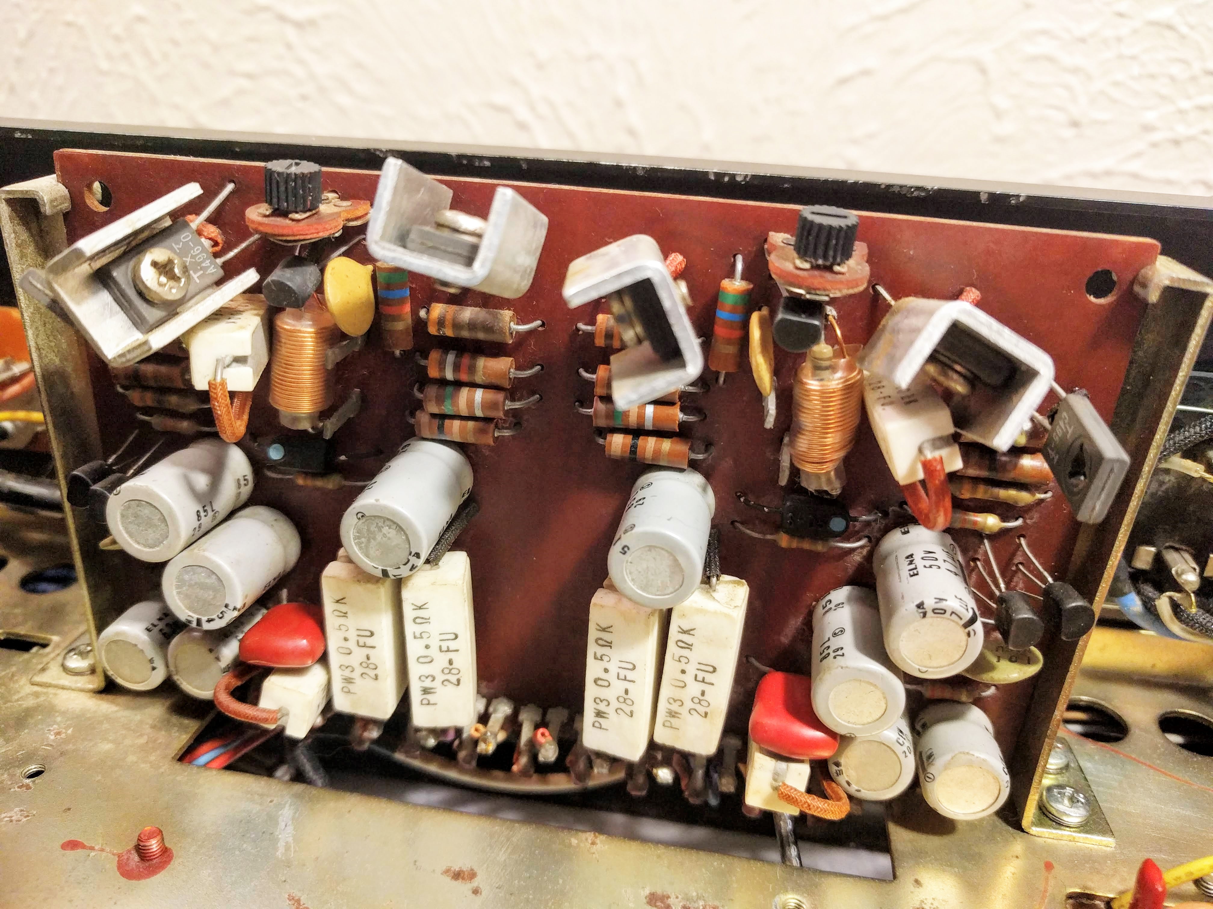
SybWemwO_o.jpg

Predriver / Driver Circuit Board Schematic

VDCnZZoD_o.jpg

Predriver / Driver Circuit Board Diagram

CVcrndKn_o.jpg

Predriver / Driver Circuit Board in stock form

Errors:
Q626 Heatsink position - The heatsink is oriented the wrong way round in the board diagram, however the pinout for Q626 is correct.

C629 - The polarity is reversed in the diagram for C629. The negative terminal should be up and to the left matching the orientation in the photo.

C609 - The polarity is also reversed for C609 in the diagram. The negative terminal should be up and to the right matching the orientation in the photo.

Predriver/Driver Board Parts List
Matching the differential pairs at Q601-Q602 and Q621-Q622 with KSA992FB lowered the offset from ~90mV as it arrived to around ~12mV afterward for each channel. Certainly worth the effort for better sound and reducing the thump during power off/on. The original 2SA564A transistors were all P rank, which was a rank below anything listed on the datasheet I found for them. The hfe measured from around 100 to 140 hFE on my tester while the replacements were 400 hFE or better.

Adjusting the bias requires an 8ohm dummy load be connected, and make sure you have the speaker selector set to the on position. The instructions for setting bias aren't as good as they should be. All you need to do is simply attach mini grabber leads to test points 1 & 2 for the left channel, and 3 & 4 for the right channel and adjust the corresponding trimmer (VR 601 Left, VR621 right) for 10mV. It would be a good idea to get some 5K trimmers to replace the originals, but I believe these were overlooked at the time I ordered. You could use a 3/8" top slot multi-turn or side slot single-turn pointed upward.

C621 220uf 6.3V 10mm Input filter >> 220uf 16V UES 10mm
C629 47uf 50V 10mm >> 68uf 63V UPW 10mm
C628 47uf 50V 10mm >> 68uf 63V UPW 10mm
C623 220uf 6.3V 10mm >> 330uf 50V UPW 10mm
C624 47uf 50V 10mm >> 68uf 63V UPW 10mm
C604 47uf 50V 10mm >> 68uf 63V UPW 10mm
C609 47uf 50V 10mm >> 68uf 63V UPW 10mm
C608 47uf 50V 10mm >> 68uf 63V UPW 10mm
C603 220uf 6.3V 10mm >> 330uf 50V UPW 10mm
C601 220uf 6.3V 10mm Input filter >> 220uf 16V UES 10mm
Q601-Q602/Q621-Q622 2SA564A >> KSA992FB matched pairs

Output Transistors (rear panel mounted beneath a vented shield)
Q901-Q904 2SD180 (T-03) >> did not change but...MJ21194G if needed
 
Last edited:
Harmon Kardon 630 Service Bulletin #165

The service bulletin pretty much speaks for itself. I'll just add the you'll want to read this first and think ahead before installing new main filter caps because of the necessity to remove the 5.6K resistor from C904 in step 3.

ukLEp79p_o.jpg
 
Great work there!

Harmon Kardon 630 Service Bulletin #165
The service bulletin pretty much speaks for itself. I'll just add the you'll want to read this first and think ahead before installing new main filter caps because of the necessity to remove the 5.6K resistor from C904 in step 3.

Just an observation.
The service bulletin most likely applies to early production run of 630 receiver.
I had 630, which I recapped and serviced few years ago. Checked the pictures, taken before I started working on it to confirm this. Later production run have this service bulletin applied on the factory I believe.
Can't rule out of the possibility it was modified by the retailer, before they made sales.

Earlier in this topic the MPX IC was also discussed.
MPX IC chip this receiver have installed is LM1307N.
 

Attachments

  • P1060282.JPG
    P1060282.JPG
    104.6 KB · Views: 141
Just thought I'd pop in and post another small discrepancy I found. On the Muting PCB, I noticed that the technical manual showed cap C715 with a value of 1uf however upon inspecting the unit, the value of this part was 10uf, 25v. See pictures below. Muting PCB_error3.jpg Muting PCB_error 4.jpg
 
I'm working on a 630 but the mur1620 rectifiers recommended are currently out of stock. Was wondering if someone can help me pick a good alternative for both of them. Thanks.

D801/803 1S1850R rectifier |<- ->| dual, common anode >> MUR1620CTRG 200V, 8A per leg
D802/804 1S1850 rectifier ->||<- dual, common cathode >> MUR1620CTG 200V, 8A per leg
 
Thats funny. I only checked the mur1620ctg, and you must have only checked for the 1620ctrg on Digi-Key

0 1620ctg in stock at Digi-Key
5885 1620ctrg in stock at Digi-Key

I looked on ebay and peace love music has some 1620 ctg. Was hoping to just get it all from Mouser to save on shipping costs. I tried to find a good alternative other than single diodes but don't want to order the wrong thing.
 
When I look at Digikey stats, they both are rated 8A per diode. Perhaps OnSemi is totaling the two legs to get 16A. Silverface notes his subs are 8A per leg, see above, and he used the OnSemi.
 
Sounds good, I switched all my items over to Digikey. I also discovered I should have been buying from them in the first place, pretty much every item was cheaper than Mouser. I knew about the free shipping option, but never knew about the lower prices.
 
I am currently in the process of picking up all the parts necessary to recap my 630 and I must say that this thread has been super helpful thus far as a baseline for what to buy! Although since this is the first receiver I have worked on I am not planning on changing the capacitance of any capacitor. One thing however that I'm a bit curious about is why you used bipolar UES series caps for C601 and C621 on the predriver board? I was just planning on using UKL once. Is there any reason why I should use UES?
 
Back
Top Bottom