• The move to the new server is done. There are some software and database maintenance updates in process. This has us passing the hat around to help out. We appreciate any donations. Seriously, even a dollar helps. The payment page may be found here - https://www.audiokarma.org/support.html

Harman Kardon 630 Twin Powered - blazing a trail

Work in progress...

Power Supply

The H/K 630 has two power transformers, three small boards, and five chassis mounted filter capacitors that make up the power supply. The three small boards are identified as "Power Supply Circuit Board", "Power Supply (Tuner and Preamp)", and "Regulator Circuit Board". According to the service manual the "Power Supply (Tuner and Preamp)" comes in two versions. My unit included version 2 so that is the one I'll be discussing.
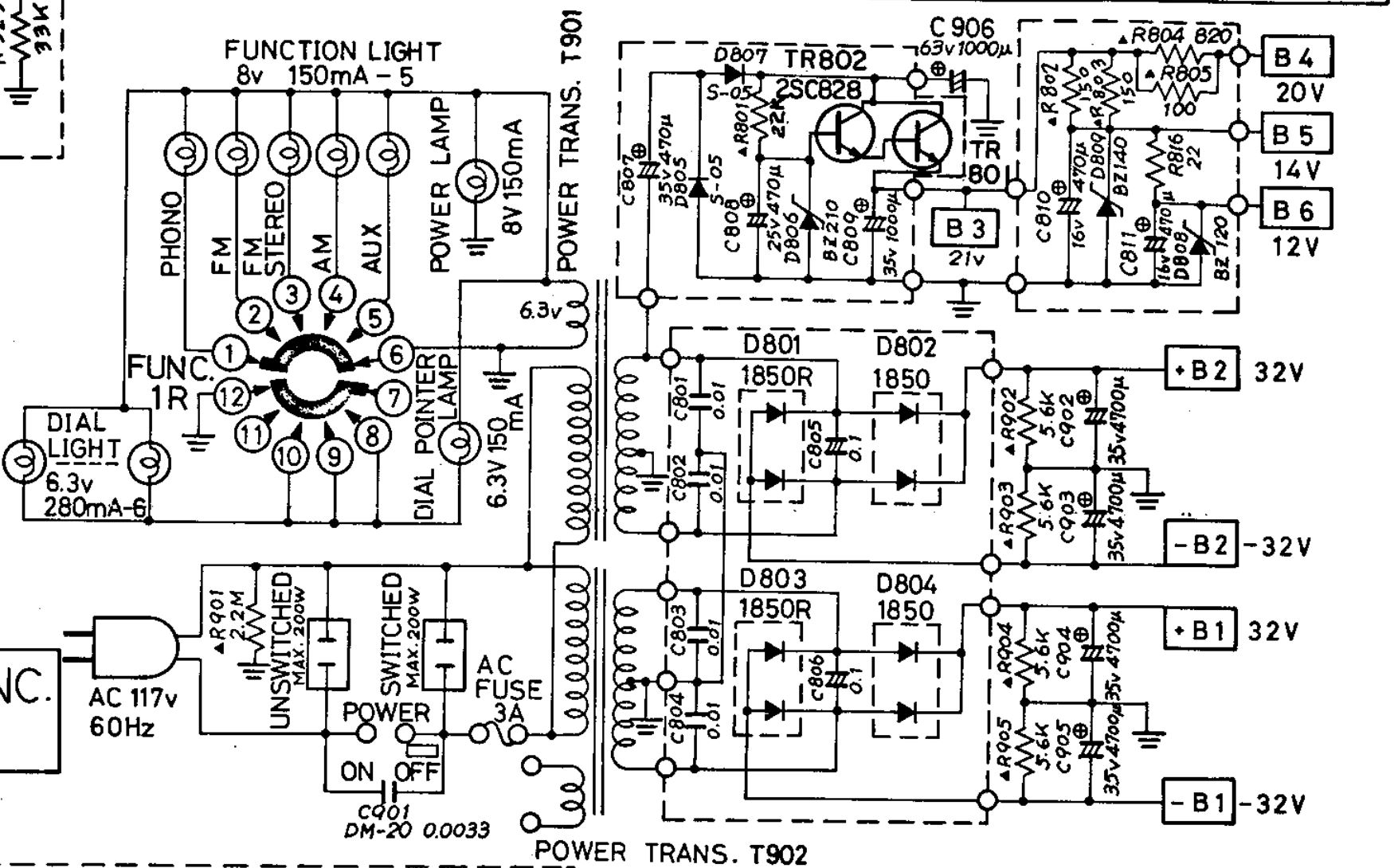
qDmMURJj_o.jpg

H/K 630 Power Supply Schematic

H/K 630 Power Supply Circuit Board (Board 1 of 3)
PUfaiVY9_o.jpg

H/K 630 Power Supply Circuit Board Diagram

kXZApC4Y_o.jpg

H/K 630 Power Supply Circuit Board Diagram in stock form

Power Supply Circuit Board Parts List
C805/806 0.1uf 400V Oil caps >> 0.1uf 400V Polyester Film
D801/803 1S1850R rectifier |<- ->| dual, common anode >> MUR1620CTRG 200V, 8A per leg
D802/804 1S1850 rectifier ->||<- dual, common cathode >> MUR1620CTG 200V, 8A per leg

H/K 630 Power Supply (Tuner and Preamp) Version 2 (Board 2 of 3)
MXuQguLB_o.jpg

H/K 630 Power Supply (Tuner and Preamp) Version 2 Diagram

1lGhsdYW_o.jpg

H/K 630 Power Supply (Tuner and Preamp) Version 2 in stock form

Error: TR802 - The pinout shown in the board diagram for TR802 is flipped 180 degrees. The front of TR802 should face the capacitors. The emitter should be on the left side closest C808 and base on the right side closest to C807.

Power Supply (Tuner & Preamp) Version 2 Parts List
TR801 is heatsink mounted with a live collector tab and needs to be insulated. Be sure to save the original insulating washer that is specificlaly designed to fit the heatsink when installing a replacement. The board diagram doesn't show the capacitor values for C807 and C808, but they are correct as provided below.
C807 470uf 35V 16mm >> 560uf 50V UPJ 16mm
C808 470uf 25V 16mm >> 560uf 50V UPJ 16mm
TR801 2SD234 TO-220 BCE >> TIP41C TO-220 BCE
TR802 2SC828 TO-126 (2SC495 pulled ) ECB >> KSC2690 TO-126 ECB
D805/807 S-05 >> Didnt change...possible sub 1N4007
D806 BZ-210 (21V 1W) >> 1N4740A (10V 1W Zener) & 1N4741A (11V 1W Zener) in series
R801 22K 1/2W Carbon Comp >> 22K 1/2W metal film

H/K 630 Regulator Circuit Board (Board 3 of 3)
8JkShnw3_o.jpg

H/K 630 Regulator Circuit Board Diagram

wi6gyEK5_o.jpg

H/K 630 Regulator Circuit Board Diagram in stock form

H/K 630 Regulator Circuit Board Parts List
C809 1000uf 35V 18mm >> 1200uf 63V UHE 18mm
C810 470uf 16V 12.5mm >> 680uf 50V UPS 12.5mm
C811 470uf 16V 12.5mm >> 680uf 50V UPS 12.5mm
R802/803 150 Ohm 1/2W Carbon Comp. >> 150 Ohm 1/2W Metal Film
R804 820 Ohm 1/2W Carbon Comp. >> 820 Ohm 1/2W Metal Film
R805 100 Ohm 1/2W Carbon Comp. >> 100 Ohm 1/2W Metal Film
R816 22 Ohm 1/2W Carbon Comp. >> 22 Ohm 1/2W Metal Film
D808 >> BZ120 12V 1W Zener >> 1N4742A
D809 >> BZ140 14V 1W Zener >>
I recently completed recapping one of these units and this thread has been a tremendous resource. Going though voltage checks, the power supply tuner and preamp board is only putting out 19.2V where is should be 21V. I'm a beginner hobbyist in the vintage audio repair arena. I have not changed any components on this board except the 2 capacitors. I am getting good +32 and -32 from the first power supply board. Everything seems to be working well with the exception of low volume on the phono section. I know the phono section typically has a lower volume but it seems a bit excessive in this instance. Normal moderate listening, I'm at about 12 o'clock on the volume dial.

Is this all normal behavior and is 19.2 close enough to the reference voltage?

If not, which components should I be looking at on the preamp power supply board?
 
Harmon Kardon 630 Service Bulletin #165

The service bulletin pretty much speaks for itself. I'll just add the you'll want to read this first and think ahead before installing new main filter caps because of the necessity to remove the 5.6K resistor from C904 in step 3.

ukLEp79p_o.jpg
Any idea what issue this service bulletin resolves? It references service bulletins #117 and #130 but I don’t have those and they may have explained the reason for the modification. Just picked up a 630 and want to do right by it. Thanks!
 
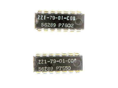
Recommend trying Consolidated Electronics (https://www.ceitron.com/howto.html) to source the LM1307 IC for the hk630 (and hk930) MPX board.
They are located in Ohio, and the guy I talked to knew old audio parts and was very helpful.
I scored a working replacement (MC1307P) for a reasonable price (3 shipped to me for $35 total - first one I tried worked).
This is their current ebay listing for the 1307 equivalent :
Please note that I have no affiliation with Consolidated Electronics, but was glad they existed.

Tom
 
According to MikesArcade.com, the MPX IC chip used here has several equivalents, so finding a usable replacement should be a little easier:

All of the following IC chips should be functionally identical and interchangeable with the LM1307N in the HK 630:​
​
ECG722 - 27 listings on ebay right now​
MC1307P - 32 listings on ebay right now​
LM1307N - 3 listings on ebay right now​
ULN2128N - 1 listing on ebay right now​
UA767PC - 7 listings on ebay right now​

15-7142C-1​
15-14471-5​
15-34049-3​
15-34049-1​
15-34049​
15-34503-2​
15-34503-1​
15-34503​

It also crosses to NTE722, which is supposedly equivalent to all of these part numbers:

0043-004793, 006B2M, 0205, 0205(DYNACO), 051-0017-00, 053, 053-1, 06B1AH, 06B1B, 06B1D, 06B1M, 06B1Z, 06B2Z, 09-017, 09017, 1043-1344, 10-47674-01, 1307H, 13-52-6, 13-52-G, 13-60-6, 15-14471-5, 15-2R51-1, 15-34049, 15-34049-1, 15-34049-3, 15-34503, 15-34503-1, 15-34503-2, 15-71420-1, 15-714201, 15-7142C-1, 170956, 1820-1110, 183014, 1C513, 2006-1, 2006-2, 21M588, 21M599, 21M600, 221-65, 221-79, 221-79-01, 26551(H.-KARDON), 26551(H.KARDON), 34049-1, 34503-1, 3533, 43126551, 431-26551A, 43126551-A, 442-16, 45381, 45381(VOFM), 4793(KLH), 51-10382A01, 51-10559A01, 51-10566A01, 51-1056FA01, 51-1056GA01, 51-10592A01, 51510566A01, 51S10559A, 51S10559A01, 51S10566A01, 51S10566A02, 51S1056FA01, 51S1056GA01, 51S10592A01, 51S1059A01, 5351041, 5351042, 57A32-10, 57A32-16, 612006-1, 612006-1M, 612006-1Z, 612006-2, 61566, 6551, 66F1181, 7021, 740-2001-307, 760522-0002, 767DC, 767PC, 905-24B, 905-38B, 905-46B, 9521, 95291, 95292, 95294, 982279, 995053, 995053-1, 99S053, 99S053-1, C6056P, CXL722, EA33X8378, ECG722, ES4053, EX4035, EX4053, F757PC, F767PC, FUA767PC, GE-IC9, GEIC-9, HEP-C6056P, HEPC6056P, HEPC6068P, IC-06-1, IC-06-1(MAGNAVOX), IC-06-2, IC-06-2(MAGNAVOX), IC-201(ELCOM), IC201(ELCOM), IC513, IC513(IR), KLH4793, LM1307, LM1307A, LM1307E, LM-1307N, LM1307N, LM1307P, LM1307PQ, MA767, MA767PC, MC1307, MC-1307-P, MC1307P, MC1307PQ, NTE722, PC-20021, PC-20024, PC-20030, PTC721, Q205(DYNACO), R1N1102, RE309-IC, REN722, RIN1102, RTN1102, SC5740PQ, SC5743P, SC8705P, SC9426P, SC9455P, SK3161, SK3161/722, SK7812, SL21864, SL22757, SL23145, SL23426, SN76107N, SN7610N-07, SN76110, SN76110N, SN76113N, SN7611N, SN766110, T1E, T1Z, T2A, T2A(MOTOROLA), T2C, TM722, TR0-9017, TR09017, TVCM-10, U6A7767394, U7F7767394, U9A7767394, UA67, UA-767, UA767, UA767P, UA767PC, UAC767PC, ULN2128, ULN2128A, ULN2128N, UPC767PC, WEP513, ZEN602​
 
Last edited:
Just pointing out a couple more discrepancies between the SM and the real world.

Main amp board resistors R603 and R623 are shown as 8.2K on the schematic and 1K on the diagram while on the board there's blue, red, red, 6.2K ones installed in these positions. This isn't an isolated incident as all three of my 630's are the same here.

Also R609 and R629 are shown as 2.2K ohm on the schematic while 3.3's are on the board.

All the rest of them on this board seem correct.
HK 630 R603.JPGHK 630 R603_.JPG
HK 630 R603__.jpg
 
did you measure it?
I did and it's a light greyish blue red red (6.2K) which measured 6.3K. But then again if it is grey, which I think it is now, that would make it a 8.2K which has drifted badly. Either way, I'll pull the covers off the other 630's tomorrow and see what they look like and take a closer look at this one out in the daylight. Thanks for pointing it out.

I think your surgery was a success and I know I should get mine done now instead of putting it off.
 
I just noticed another small issue with the schematic. The 2.2K resistor coming off the base of TR 602 is marked as R 609 on the schematic while it should marked as R 607. The real R 609 is a 3.3 ohm off the collector of TR 605. The schematic for the other channel shows it correctly as R 627. Not noticing this earlier in my previous post might have caused some confusion.
HK 630 Amp Schematic.JPGHK 630 Correction.JPG
 
Adding a note here for something I found on the 630 I am working on. I just did the tone board and all of the 10uf caps on the board were different than what others have had. All ten of the 10uf caps were these 25v 10uf Bipolar caps, all of them. I didn't know what to make of that, a design improvement, they had a bunch to get rid of, or they were getting too many polarity mistakes in assembly. I don't know? The bipolar caps were pretty big, but even so I had a tough time getting Wima film caps of 10uf in, I had to move 7 resistors to the back of the board, and four of the bipolar caps I had to use an electrolytic replacement - I just could not make it fit. I did get films in for the input and output though as suggested by the OP. Not sure if the bipolar route was needed, but I just did it cause that was what was in there. Here is a pic of a few of the old 10uf caps.

tone_board_caps.jpg
 
I did not see this on the hk630 I recapped (nor the hk930, hk430 or hk330c)
I have stooped to mounting caps on the solder-side of the board if not fitting on the component side.
 
That trick does work sometimes. The 10uf wima films have very short legs, with large bodies, not good candidates for bottom mounting. Also on the 630 the bottom cover is right below the tone board, clearance is an issue.
 
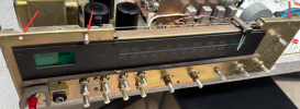
I bought a nice-looking 630. One of the wafers of the rotary switch is broken. I have another one here that doesn't look as good, but the switch works. I want to use the switch from this one. Can anyone tell me how to disassemble the front panels so that I can access the nut to loosen the switch?
 
I bought a nice-looking 630. One of the wafers of the rotary switch is broken. I have another one here that doesn't look as good, but the switch works. I want to use the switch from this one. Can anyone tell me how to disassemble the front panels so that I can access the nut to loosen the switch?

To remove the 630 face you'll first need to remove the top and bottom covers, Once thats done you need to remove all the knobs.
Most of the knobs just pull off but the Bass/Treble require a small flathead to release the set screw that holds the outer part of the knob.

After you have all the knobs removed there then there is 3 screws across the top and 2 across the bottom that need to be removed :

2025-12-20_12-49-37.png

For these sometimes the standoff will unscrew from the face, you can see with my one, if this happens you can separate the screw from it with pliers
and then it screws back into the face with a flathead.

Hope this helps a little, just go slow and its pretty easy, be very careful around the dial pointer.
 
Last edited:
Good morning! Does anyone have detailed photos of the selector switch showing where the cables are connected halfway through?
 
I am currently in the process of picking up all the parts necessary to recap my 630 and I must say that this thread has been super helpful thus far as a baseline for what to buy! Although since this is the first receiver I have worked on I am not planning on changing the capacitance of any capacitor. One thing however that I'm a bit curious about is why you used bipolar UES series caps for C601 and C621 on the predriver board? I was just planning on using UKL once. Is there any reason why I should use UES?
I assume just because UES are good for audio path. For what it's worth I used 220 uF 35 VDC UKL1V221KPD for C601 and C621 when recapping mine and it sounds great to me.
 
IMHO, hard to go wrong with Nichicon UKL for signal path applications.
Low leakage is less important in the main amp vs the phono EQ or preamp, but no harm.
The bummer is that these are phasing out with mostly only high voltage ones still available on DigiKey or Mouser.
I have stocked up as I could and wonder what we can use post-UKL for values > 6.8uF where film caps get too large.
 
I have not, but an interesting option. The leakage spec is 0.002CV or 0.4uA (whichever is greater)
1773289444090.png
The .002CV matches the Nichicon UKL, but the added min of 0.4uA is significantly worse for smaller capacitance at lower voltages
example : 10uF at 10V would be (0.002)(10 x10^-6)(10) = 0.2 uA for UKL but double that for TWL (0.4uA min)
Still, this is the best alternative I have seen proposed and Rubycon looks like a quality vendor out of Japan.

Also interested in experiences other have had.
 
Super helpful thread. I received the 630 rebuild kit from Ben and am about to work on the Power Supply (Tuner and Preamp) Version 2 board. Ben’s instructions (and everything on this thread) indicateTR802 is supposed to be either 2SC828 or 2SC495 to be replaced by KSC2690. However, on my 630, there is an RCA 6284 in that spot. I think I’m fine replacing it with the KS 2690, but I’m wondering if someone replaced TR802 with the RCA 6284 or if it came from the factory like that. Everything is working, I’m just making sure it keeps on keepin’ on. It’s on my nightstand next to my bed, looking great in its wood case and lulling me to sleep. I like that it has function indicator lights while my 730 does not. Any thoughts about the RCA 6284 would be much appreciated. Cheers!
 

Attachments

  • 1774328860565.jpeg
    1774328860565.jpeg
    109 KB · Views: 10
Back
Top Bottom