• The move to the new server is done. There are some software and database maintenance updates in process. This has us passing the hat around to help out. We appreciate any donations. Seriously, even a dollar helps. The payment page may be found here - https://www.audiokarma.org/support.html

Harman Kardon 900+ Repair

Jaman87

New Member
All-

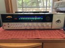
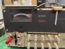
I have picked up Harman Kardon 900+ Quadraphonic Receiver. I know, I know. But I was able to negotiate a fair price and I couldn't resist. There are a couple features about it that I really like:
  • Quadraphonic / Stereo switch. In the stereo mode, this bridges the amplifiers and give me 90 RMS/ch into 8 ohms. I think this is as close to a Harman Kardon Citation Receiver as I am ever likely to get.

  • Apologies to the purists that don't like tone controls, but this one gives me a mid-range tone control. The mid-range tone control while not exactly rare, usually appeared on only the high end products of the different manufacturers. My friend had a big Marantz that had the mid-range control and it spoiled me. Yes, I could get a multi-band equalizer, but it is just one more thing, and the mid-range control is good enough for me. Besides, She-Who-Must-Be-Obeyed (SWMBO) is already intimidated enough by the controls I already have, (although she gets over her intimidation long enough to turn the volume down, once she learned the difference between the tuning control and the volume knob).

  • It is visually pleasing. The display is classic Harman Kardon green, but instead of just green you get orange and purple as well. It has a wood case, that is its own restoration project.
So what are my short term objectives? I would like to get it running well enough to explore the world of Quad, using the built-in SQ and CD-4 decoders. Long term, not sure. I am not committing to a restoration job. Just yet.
 
Register to hide this ad
Do basic checks and servicing...cleaning/lubing switches and pots, check what traces you can see for bad solder joints, check the component side of the boards for heat stress/ browned areas, bulging caps or those with shrunken sleeves and or any corrosion due to glue becoming corrosive to components, check DC Offset and adjust if able, check/set bias per the SM. Then, if those things can't be done, start by checking voltages off the PS board...bad volts out, problems downstream.
 
What did I get?

Whenever I buy a vintage receiver, first I shake it and turn it over to listen if there are any parts loose in the case. I once found a screw rolling around inside. Not exactly a good situation when high voltage is concerned. It was dirty with grimy knobs and nicotine stains. Then I check the fuses (if present). Sometimes a fuse is missing. Very often they are the wrong type and amperage rating. You know people, God Bless them. "Blew a fuse? It must have been old. Gee, I don't think I have any glass fuses...wait a minute, (rummages through the junk drawer), Aha! this 20 amp fuse will fit. Or they resort to real skullduggery where they wrap the fuse in aluminum foil and put the fuse back in. People, bless their hearts. There was also a speaker fuse cap missing. I thought alright I will buy some new fuse holders off the the well known on-line auction site, Who-Shall-Not-Be-Named (WSNBN). But I found out when I got them that even though they look the same as the original ones, they are not the same. I finally got one that fit.

The dial lights are all working. One bulb is out on the "Quieting" meter, an interesting combination of a signal strength meter and a tuning meter. Then I blew it out with Clean Compressed Air and looked for signs of corrosion, then on to the dim bulb tester. No Variac because I don't have one. The dim bulb test was open to interpretation. No dead shorts, but the bulb glows a little more than I think it should, but I only have a 75 watt incandescent bulb, so maybe this is okay.

I decided to start testing it. The switch was placed Stereo mode. The on/off button pilot light is burned out. The FM works...on one channel. Same with the Aux Function. Okay then, time to clean the potentiometers, rotary switches and push button switches as I could tell they are very gunked up. The question is how? I can't get to them from the top or bottom. I removed the potentiomenter locknuts, and removed the mounting screws for the tone control board. Because the wires to the board are soldered to the back edge of the board, I was able to fold back the tone control board so that the tone controls pots are exposed. I cleaned them with first with Deoxit Dn5 followed by Dioxit Fader F5. I found that I could get at the push button switches at some very awkward angles and repeated the cleaning on them. Thank goodness, because I'm not anxious to try to remove these switches. I used the Dn5 on the rotary switchs and I was able to get to the volume pot as well. So I put this all back together, back on the Dim Bulb tester and same as before. I removed the dim bulb and turned on the FM receiver and ....I now have 2 channel audio working on both front and remote speaker banks! Sounds pretty good. The only strangeness is that after you press the on/off switch, it takes about 15 seconds to hear any sound and 20 seconds to hear full stereo audio. When I turned it off, there is a loud pop on the left channel. Thinking the slowness could be that the power supply capacitors are beat, I ESR tested all of the ones I could reach and a significant number of them of indeed outside of the expected ESR Value. I placed an order with one of the big two component houses WSNBN.

Before changing out components, I decided to get the lights working. The Quieting Meter has a reflective metal housing on the back of it to support to support the two bulbs. These bulbs stab through the back of the housing and are held in place by rubberized metal grommets that promptly disintegrated as I removed them. This housing must have been wet at some point and was completely rusted out. See the photo below:
bdbfd7f2-97a6-4739-805e-04b240980f04[1].jpeg

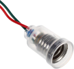
The lights were baseless with leads sticking through the glass. I just couldn't live with these things so I decided to install E10 screw sockets with E10 LED bulbs in the housing.
1754016011611.png

I drilled out the holes from 15/32 to 33/64, sand blasted the housing and painted with bright cadmium paint from a well known automotive paint company WSNBN.
6bec2413-9c31-4867-952c-326cd667a94c[1].jpegbcc93b17-a8a3-4397-b68e-48fbc4a5e8a7[1].jpeg

I used JB Weld to spot glue them into place. The sockets stick out pretty far and interfere with the filter caps. But with care, you can set the housing into place.
1aa6c321-616a-4058-b89e-554a52c6505d[1].jpeg These light connections to the receiver are on the dial light board. But because the board is too tight to solder, and requires major disassembly to get dial light board out, I cheated and trimmed the leads of the sockets and the leads to the board, solder spliced them together and covered the splices with heat shrink tubing. I also repaired the on/off pilot light,no splices needed. I think it looks good now.
b45f1fc1-60b6-446c-a814-1e6b0ea44a00[1].jpeg
 
Do basic checks and servicing...cleaning/lubing switches and pots, check what traces you can see for bad solder joints, check the component side of the boards for heat stress/ browned areas, bulging caps or those with shrunken sleeves and or any corrosion due to glue becoming corrosive to components, check DC Offset and adjust if able, check/set bias per the SM. Then, if those things can't be done, start by checking voltages off the PS board...bad volts out, problems downstream.
Thank you jheu02.
 
I am not committing to a restoration job. Just yet.
Kinda looks like you are. :rflmao:

a 75W bulb with a 90W receiver probably will glow a little. But since you later plugged it into the wall for listening tests and it didn't blow up, I'd use a higher wattage bulb in the future. To aid in disassembly, some chassis have a couple screws on the side that hold the front in place. By removing all but one (to act as a hinge once loosened) the front panel will rotate forward. This may or may not be the case with the 900+.

As to the delay in sound, it doesn't appear to have a protection relay, and H/K units of that time frame seemed to use what they deemed a "soft-start" circuit, usually made up of a transistor and a couple capacitors. It does seem a bit excessive at 10-20 seconds, but moreso because it's one side, then the other. There's a bunch of 2SC458s in the 900+...looks like some COULD be replaced with KSC1845s, but some may actually need the current handling capability of the 458, so may need to use something like the KSC1815 there. Loud pop at power off sounds like the power switch still needs cleaned. Oh, one more thing, in your last pic, I don't see the power light on. Thought you said you replaced it.

Lots of work ahead....
 
Yes I chose that other photo to show the lighting on the Quieting Meter. This one shows the power lamp.

1205161b-abaa-4fda-9dbe-f554803b893d[1].jpeg

So that brings me back to what is going on with the power consumption. When I have it set to FM Stereo and the dial lights are on, this is the power consumption.1dcdcfda-9dc7-4d1f-a577-aa160dce3b35[1].jpeg
This seems like a lot of wattage for a receiver that is at idle.Then when I set it to Aux, and the dial and lamp meters are out, I see this power consumption.
ccbda026-8030-46fd-b80d-06a4a8066a85[1].jpeg c467c2ab-e55d-456d-9f49-4752b19dcadf[1].jpeg
Should the FM section and lighting make this much of a difference in power consumption?

100W incandescent bulbs are hard to come by. What is a good source for them? I do have a 120W incandescent flood light. I suppose use that?
 

Attachments

  • 1205161b-abaa-4fda-9dbe-f554803b893d[1].jpeg
    1205161b-abaa-4fda-9dbe-f554803b893d[1].jpeg
    18.6 KB · Views: 18
Last edited:
Your small pics are hard to see details in. If they're uploaded directly to AK, you can make them Full Size vs Thumbnail. The lighting, especially incandescent, will add to the current and wattage, but I don't have a meter like the one shown to try it on my gear.

I use a 60W bulb for lower powered gear (sometimes even a 25W for things like Tuners, Preamps) and a 150W for higher powered gear.
 
Here is the power supply board. I have measured as many of the capacitors as I could.
975e6002-1444-4657-92f0-175ecf4281b3[1].jpeg
Here are the ESRs for the caps I can reach. I am certainly going ro replace the bad one. A few of these have good ESRs, but because they are esay to reach, I should probably replace them anyway. Of course there are the one I cannot reach without removing the board. I know this is a whine, but I am not anxious to un-solder All those wires. It will be time consuming and on a few of them there isn't much strain relief.

Size (μF)Cap No.ESR (Ω)
2200C8210.48
1000C8150.68
1000C8110.33
470C7070.24
100C8180.13
100C8200.17
100C8190.18
100C8120.20
 
That last pic is much better. Boy do I hate axial electrolytics....much easier to find quality radial caps and NOT have to add extensions. You have the ESR listed, but not leakage or capacitance. Often they drift high and or become leaky. That said, even if they seem to measure OK, they're not being tested at rated voltage, and they're 50 years old at this point. I replace them for preventative purposes more than anything.
 
Last edited:
It’s been a bit since I last posted to this thread so I thought I would give an update.

My testing of the Harman Kardon- 900+ has been mostly listening in the two-channel mode to see what is working and how it sounds.

I have spent a while listening to FM and its different modes (Stereo, Mono, Enhanced Stereo). The FM function sounds good, with a good stereo image. I believe the tuning is slightly off so an FM alignment may be done sometime in the future. The FM has been connected to an indoor Radio Shack amplified antenna. Tuned to a strong station, the stereo light comes on and the soundstage is clear. The left and right channels seem well separated, with the right channel seeming a little quieter than the left channel. A very slight shift in the balance control puts things right and sometimes they sound fine with neutral balance. The volume turn-down is uneven at the low end of the potentiometer's range, where the right channel fades out before the left channel. Turning the volume down further, the left channel drops out abruptly with some range left on the volume control. Compared to a couple of other receivers I own, the 900+ FM tuner doesn’t seem as sensitive in that it pulls fewer in stations on FM Stereo. I replaced my pilot lamp with an LED but it stopped working. I traced this back to a bad solder joint (my bad) on one leg. So, I pulled off the bottom, removed some of the solder from the connection, re-soldered the connection and the pilot lamp is back. The stereo indicator lamp was always working and even though it looks original to the unit, I left it in place. On the other hand, the separate “In Tune” lamp stopped working. I replaced that one with an LED and… it still doesn’t work. However, I have something like this going on with another project where the replacement LED doesn’t work. It has dawned on me that being diodes, they are polarized, and I have installed them backwards. (DOH!) This one is still on the list to be corrected.

IMG_2060.JPG


The CD Player on the Aux function sounds very good. However, the playback on the turntable (Phono 2) is not so good. The bass and mid-range sound okay but the high frequencies sound very harsh and shrill. Not distorted but more like the treble is way too high and is too sharp to listen to for very long. The high cut filter works, but it de-emphasizes the high frequencies too much. Turning down the treble control from neutral helps. The high frequencies are softer but still pretty annoying. Phono 1 sounds better but the treble is still too bright, so I think a rebuild of the phono pre-amp is needed.

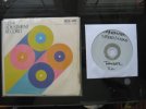
I purchased a JVC CD-4 calibration vinyl record, from that auction site, I didn’t mention earlier. I was surprised a CD was also included with the record. I assume it is a rip from the record. I wonder if the CD has the high frequency encoding for the CD-4 Quad mode . I am anxious to try out the Quad mode. I am not sure if my Ortophon Red phono cartridge is up to this, but we will see. First, I am going to set the bias and measure the DC offset to see what I have. I will update on what I find.

IMG_4285.JPG

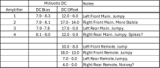
I have checked the bias and the off set. Please see the table below.

1756474631577.png
IMG_4287.JPG
The bias readings were initially very low at about 1 mV. The instruction in the manual say the bias should be set at 8 mV. When I tried to adjust the readings, the potentiometers either couldn’t reach the desired setting or were just impossible to set. I decided to clean them with Deoxit D5n and lube them with Deoxit Fader F5. This helped a lot. One turn pots can be tricky to adjust, but the last thing I want to do is replace these trim pots. My overall impression is that the readings were sort of jumpy, so I have represented these as ranges. The values themselves seem to be good. Sometimes, I think there might be spikes that my DVM has trouble representing. Perhaps it is time to get out the new Oscilloscope and look at this?

Next, I think I will try to fix that “in-tune” lamp and then listen to it for a bit, while I attend to other projects and “Honey-Do’s”, while contemplating a rebuild of the power supply board and the Phono preamplifier. I am interested in comments and suggestions from the group.

IMG_2135.JPG
 

Attachments

  • IMG_4283.JPG
    IMG_4283.JPG
    89.6 KB · Views: 4
  • IMG_2060.JPG
    IMG_2060.JPG
    118 KB · Views: 2
Last edited:
Back
Top Bottom