• The move to the new server is done. There are some software and database maintenance updates in process. This has us passing the hat around to help out. We appreciate any donations. Seriously, even a dollar helps. The payment page may be found here - https://www.audiokarma.org/support.html

Harman Kardon A-402 Restoration

LED Driver and Control Boards The Control board also holds the 470 ohm 1W resistors for the headphone jacks. I was originally going to replace these with Dale RN60s for added clarity, but when I pulled the originals and measured them, they were nicely matched and had nice copper leads (discovered while using a rotary tool to wire brush the leads), so I reinstalled them. Also, though the scat shows C13/14 as 220uF/16V, the light blue TK caps actually installed were 25V.

LED Control Pre
50063918292_95d3af8e57_o.jpg


LED Control Post
50063658966_07c4612304_o.jpg


LED Driver Boards Pre
50063918032_abef9a144c_o.jpg


Post
50063918237_3bf92dbc9a_o.jpg

50063918117_a2bbd964c8_o.jpg
 
Question regarding the power light, which not surprisingly is burned out, It's a 9V/65mA T-1 3/4 base incandescent. Easy enough to replace with this bipin incandescent.
https://www.mouser.com/ProductDetail/560-7371

Would this LED work as a replacement, and if so, how do I implement it. I know a resistor and possibly cap or diode may be needed, but I've never done an LED "upgrade".
https://www.mouser.com/ProductDetail/Cree-Inc/C513A-WSS-CX0Z0341?qs=ua4hIysp8dLUxsfUQjF8XA==

Would this one even need a resistor since it's 12V?
https://www.mouser.com/ProductDetail/VCC/LTH5MM12VFR4400?qs=Mv7BduZupUj4KjguY6Dr0A==

A402_PS_Scat_Lamp.jpg
 
Question regarding the power light, which not surprisingly is burned out, It's a 9V/65mA T-1 3/4 base incandescent. Easy enough to replace with this bipin incandescent.
https://www.mouser.com/ProductDetail/560-7371

Would this LED work as a replacement, and if so, how do I implement it. I know a resistor and possibly cap or diode may be needed, but I've never done an LED "upgrade".
https://www.mouser.com/ProductDetail/Cree-Inc/C513A-WSS-CX0Z0341?qs=ua4hIysp8dLUxsfUQjF8XA==

Would this one even need a resistor since it's 12V?
https://www.mouser.com/ProductDetail/VCC/LTH5MM12VFR4400?qs=Mv7BduZupUj4KjguY6Dr0A==

View attachment 1913435

There are LED's that are direct replacement. All my receivers have been upgraded with such. I will dig out the name of a very reputable and knowledgeable Ebay seller that am sure will be willing to sell you a single LED. Otherwise you can buy a kit for the HKX30 series and use the power button LED only.
 
I'm already placing a Mouser order for caps, etc, so don't want to pay an extra shipping fee and the hassle of more than one order. It's including parts for several projects, so looking at lots of different things. Thanks though.

What would be a big help, since mine is torn apart right now, is also taking a voltage reading going to the pilot lamp from the L transformer secondary winding. The SM doesn't list it, but I'm guessing it's around 8V since the bulb is listed as 9V.
 
Last edited:
Question regarding the power light, which not surprisingly is burned out, It's a 9V/65mA T-1 3/4 base incandescent. Easy enough to replace with this bipin incandescent.
https://www.mouser.com/ProductDetail/560-7371

Would this LED work as a replacement, and if so, how do I implement it. I know a resistor and possibly cap or diode may be needed, but I've never done an LED "upgrade".
https://www.mouser.com/ProductDetail/Cree-Inc/C513A-WSS-CX0Z0341?qs=ua4hIysp8dLUxsfUQjF8XA==

Would this one even need a resistor since it's 12V?
https://www.mouser.com/ProductDetail/VCC/LTH5MM12VFR4400?qs=Mv7BduZupUj4KjguY6Dr0A==

View attachment 1913435

the grand overkill path would be what I did for the dial pointer:

tiny rectifier bridge feeding
Small reservoir cap feeding
3.3v voltage regulator feeding
One of those small LEDs

https://audiokarma.org/forums/index...s-stereo-receiver.887627/page-2#post-13144207

you could accomplish the same with a diode or two and a small cap to prevent the LED from flickering (due to AC) and a resistor to drop the voltage to whatever the LED wants.

there is a super-useful LED resistor calculator that I use for this kind of thing: http://led.linear1.org/1led.wiz
 
You might as well use the already rectified and smoothed DC from across C10. Plug the DC value into the resistor calculator Doug posted above, together with the forward voltage and current that your chosen LED takes. You can then add this resistor in line with the anode wire, and cover it in heat shrink. Depending on the brightness and/or viewing angle of your LED, you might want to sand the case down carefully in order to diffuse the light somewhere. Have a look at the post below, and scroll down to post #23. You can see how the LEDs I used on this Technics amp have a kind of frosted look to them. This helps diffuse the light and make it less directional.

https://audiokarma.org/forums/index...ng-for-preventative-maintenance.771362/page-2
 
Would it be better to tap at C10 or just the B3 +/- wire wraps? I wonder why H/K (with all the other LEDs for the power meters) chose to use A/C incandescent for the pilot lamp? The bulb just lights up the transluscent red power button extension, so I don't know how important diffused light is, but easy enough to rough up the bulb.

A402 Sub_rec_LED_Pilot_Mod.jpg
 
Last edited:
Lee...trying to learn. Why there as opposed to what's coming of the full board?

Your LED doesn't have to have a fully regulated supply that you would get from +B3. It makes no real difference though. I don't know if that helps you or not...
 
I wondered if it could mess up what's being fed to the LED drivers for the meters by adding something else. I also figured it would be easier to just tack the bulb wires onto the wire wrap posts vs a hole in the board even though the holes are already present.
 
Switch Cleaning

I've disassembled other types of switches for a good manual cleaning, so wanted to try the same for these before resorting to Doug's drill method. Found out they're pretty easy to open, at least the ones that aren't part of the meter display LED panel. It requires no desoldering of the switches from the board and for a chemical/physical scrubbing of the inside contacts using a pipe cleaner soaked in some deOxit. A Q-tip is a little big unless it has the plastic stem and can be squashed before inserting. Hopefully this will really aid in cutting down the channel dropouts this model has a bit of a history with.

Mode A Switchboard removed during recap and switch cleaning. Wires still connected to rest of amp.
50069131426_9cbce15c5a_o.jpg


Opening push button slide assembly
50069131346_a99a62f777_o.jpg


Pin removed
50069388842_f28a5377ab_o.jpg


Slide contacts now exposed for cleaning. Main body internal contacts cleaned with deOxit soaked pipe cleaner. Follow up on slider contacts with deOxit gold for long term protection.
50068576343_04cc0af7b8_o.jpg


All clean
50069131151_043c9a3124_o.jpg


Reassembly
50069257111_28faf81724_o.jpg
 
Last edited:
Still haven't figured out the meter switches. They're interlocked (pressing one, disengages any that are engaged) so only one switch can be active at a time. So, that probably has something to do with it. But since it appears that they get the signal tapped off at the speakers, slight dirtiness shouldn't affect the sound or channels dropping. Been cleaning the selector switch. The trace side of the board (facing up into the chassis) was filthy from collecting dust over the years, but looking better now. It looks like I'll have to desolder it if I want to change out the input resistors to the Dales, but that's where all signals enter the audio path to the rest of the amp.
 
Got the Selector Switch board all cleaned up as best I could. I decided to try and remove the switch from the board so I could replace the input resistors and also really get the the contacts clean. Thick, double-sided board is all I can say! :yikes:

Despite my best efforts with the Hakko desoldering iron in combination with desoldering braid, I could NOT get the holes clear enough to remove the switch, I was able to get the resistors changed out once I removed the back shield. Lots of D5 and the cheaper Caig contact cleaner/flush brushed in with a clipped watercolor brush and pipe cleaners. Followed it up with some G100L brushed on.

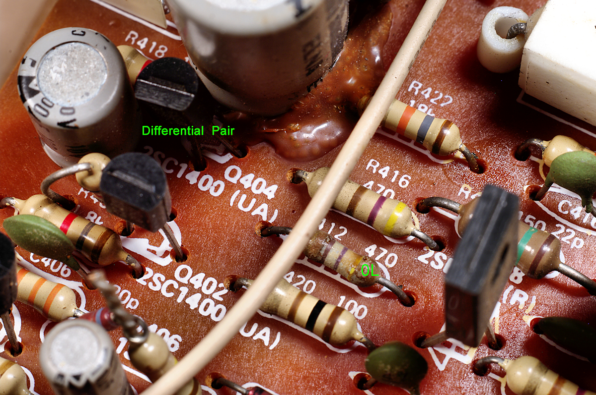
Then removal of the heat sink/amp board. Needed liquid wrench to get the screws holding the heatsink to the chassis free so that I didn't strip the Philips head. I wanted to get a little initial desoldering done in prep for the mouser order to arrive. Once free I could see that it's definitely been worked on before and I may have figured out why the DC Offset is over 100mV. Holding the board up to a bright light source I could see some open solder holes, but on each amp channel, one of the two resistors that feed the differential look bad and not OEM. I did pull one for the left channel and it reads open... So, there will be some more desoldering/testing of components, but I may not need to change out the differential 2SC1400s for KSC1845s. Not that I might not do it some day, but I do want to see if the offset issue was related to the bad resistor(s).

Now to decide whether to go with 464 ohm or 475 ohm in the Dales or use 470 ohm MOX...

R Amp Differential R411 definitely not original, and most likely open.
50073187623_7f43455555_o.jpg


L Amp Differential. R412 tested open out of circuit.

50073187708_db4d2ee837_o.jpg
 
Well, just a word of warning: when the 2SC1400s “go noisy” and run some shot noise into your speakers AT FULL VOLUME....

noisy transistors in a preamp stage are one thing, but noisy transistors in a power amp stage are a different level of risk.
 
Thanks for the warning. Have you gotten a really good listen to the amp stage of the 730s PRIOR to replacing transistors, etc? I'm surprised I was able to listen at all after seeing open resistors and some definitely sketchy contacts on the amp boards. Sound was fine, but only a brief listen. Some of the dropouts/distortion at first could be attributed I guess to the poor soldering done previously.

EDIT:

The 1845s look to be a drop in replacement (ECB), I just don't really feel like matching any up right now, but will I guess....

EDIT #2...

R411 (the other non-OEM R) is also open.
 
Last edited:
Sure. The phono EQ board is very easy to remove. Thanks for the offer.
I will have some time either tomorrow or Monday to look into it.

Now that you have gone throughout the entire amp you may or may not have more questions/concerns. Please, give me a list of things that you would like me to check/take pictures of.

Best

Soundork
 
Back
Top Bottom