• The move to the new server is done. There are some software and database maintenance updates in process. This has us passing the hat around to help out. We appreciate any donations. Seriously, even a dollar helps. The payment page may be found here - https://www.audiokarma.org/support.html

Harman Kardon A300 / A30K Redplating

David_NC

Super Member
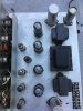
I recently posted about buying a partially recapped A30K (kit version of the A300) in really nice shape. It had been recapped, other than for the 3 multi cap cans. I did not want to power this on without replacing these caps after experiencing one non-replaced cap explode in a Pioneer receiver. This particular unit has four 6V6GT's - two Maganavox and two Sylvanias, thought all look the same (other than the logo). These have medium dark grey finish to the glass, other than for the very top.
I replaced the power supply caps Monday night and checked over my work a dozen times at least. Yesterday, I ran it at 1/4 and then 1/2 power on a variac (I'm always nervous plugging these things in after I've worked on them!) Next, it went on a DBT, and all looked well. I then tried it with normal power and an audio input, and it sounded really nice. I moved it from my test speakers to a pair of normal speakers and was happy with the sound. I did notice the top of one tube was slightly brighter than the others, but I couldn't see inside due to the dark glass; plus, it was sunny and quite bright out, and I was working with the garage door open.
Last night, I moved this amp to my garage system and got ready for some listening. Initially, it sounded great. Then, I noticed one channel was slightly softer than the other and was a bit fuzzy sounding. That same tube was bright on its top. I turned off the amp and swapped that tube with it's partner. The second tube in that same socket was brighter on top.
I did not replace any resistors in the amp, but I tested them, and all were within spec. I also replaced the two diodes. The only other thing I noticed is that a pair of 12AX7's was slightly dimmer than the others, if that means anything. My tube 'repair' experience is this amp and a Dynaco ST-70 that I recapped and did the usual to (resistors, rectifier, etc) to last year. The symptoms plus the fact that the amp 'works' makes me think I didn't do anything wrong with the caps but that there is an issue with something else. Any hints or suggestions would be appreciated!
(edited to correct the output type to 6V6GT)
 

Attachments
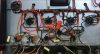
  • IMG_1421.JPG
    IMG_1421.JPG
    168.4 KB · Views: 80
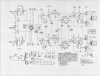
  • A300 SCHEMATIC.jpg
    A300 SCHEMATIC.jpg
    120 KB · Views: 79
  • Top - Angled.JPG
    Top - Angled.JPG
    117.4 KB · Views: 74
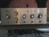
  • Front.JPG
    Front.JPG
    77.5 KB · Views: 74
Last edited:
Register to hide this ad
bad coupling caps, a partially shorted cathode cap, or just gross imbalance in the tubes is all that comes to mind. If the caps are all new, tube problems would be my guess. If one or more is weak the others will try and carry the load and it tends to go badly. This one really needs a matched quad to behave itself properly.
 
+1 on gadget's input. One other thing. The A30K calls for 7408 tubes, which are an up-rated version of the 6V6. The 7408 has 14w max plate dissipation rating vs 12W for the 6V6/6V6G/6V6GT type and the voltage ratings are significantly higher for the 7408. From what I can tell from your schematic (the numbers are a little hard to read), the plate and screen voltages are above the max limits for the 6V6/G/GT under normal operating conditions. By the datasheet, the 6V6GTA should have same ratings as the 7408, so those would be ok. Just FYI.
 
bad coupling caps, a partially shorted cathode cap, or just gross imbalance in the tubes is all that comes to mind. If the caps are all new, tube problems would be my guess. If one or more is weak the others will try and carry the load and it tends to go badly. This one really needs a matched quad to behave itself properly.
I was thinking tubes as well, but the issue stays with whatever tube is that one socket, which is why I was thinking (hoping) it prob wasn't the tubes. Would swapping the pair in the suspect channel's socket with the other pair be of any use? I'll see if I can get them tested, at any rate. Coupling caps are only a couple years old, but I suppose they could be be bad. It wouldn't be a big deal to replace the coupling caps to the output tubes, if the tubes test fine.Should the resistors at the sockets be replaced as well, even if they test OK? I'm not sure how much their actual values change when hot.
Reading the below, from http://shermanr.web.prw.net/Page_02.htm, made me wonder if any of it could be the cause (again, it's all foreign to me).
"But the unique Cathode Biasing scheme merits mention and specific attention. If you examine the Schematic you will see that there is no Cathode Bias resistor. You may ask then, how can we Cathode Bias the output tubes without a Cathode Resistor ? Well by a trick of the trade, using the input tube filaments as 'surrogate' Cathode Bias resistors. The HK designers realized that the proper bias current for the four 7408/6V6GT output tubes was about 37 milliamperes DC for each tube. If you multiply this by four, you arrive at 150 milliamperes total cathode current. The proper Cathode Bias Voltage just happens to be 24 Volts DC, which is two 12AX7 filaments in series wired as 12.6 Volts (Pins #4 and #5) , not 6.3 Volts (Pins #4&5 tied together and PIn #9). Ohms law states that the Series Current through a loop is equal though each discrete series element. Coincidentally, this biasing scheme makes the perfect "Cathode Bias" solution with the added benefit of using the DC Bias Current to feed the 12AX7 filaments DC. A symbiotic relationship that was also used in the A500 amplifier as well."
​
+1 on gadget's input. One other thing. The A30K calls for 7408 tubes, which are an up-rated version of the 6V6. The 7408 has 14w max plate dissipation rating vs 12W for the 6V6/6V6G/6V6GT type and the voltage ratings are significantly higher for the 7408. From what I can tell from your schematic (the numbers are a little hard to read), the plate and screen voltages are above the max limits for the 6V6/G/GT under normal operating conditions. By the datasheet, the 6V6GTA should have same ratings as the 7408, so those would be ok. Just FYI.
I didn't post the current outputs correctly. They are 6V6GTs, not standard 6V6s. I should update that in my OP.

Thanks for the replies.
 
6V6GTA has higher ratings than 6V6 or 6V6GT. You need the GTAs in an A30/A300.

That said- I bet it's a coupling cap problem, or a grid-ground resistor issue, on that output tube socket.

Regards,
Gordon.
 
6V6GTA has higher ratings than 6V6 or 6V6GT. You need the GTAs in an A30/A300.

That said- I bet it's a coupling cap problem, or a grid-ground resistor issue, on that output tube socket.

Regards,
Gordon.
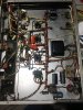
Resistor check will take place shortly. As for the coupling cap in question, here's a better pic of the area with the socket in question circled:
Bottom - Zoom.jpg
Which is the coupling capacitor for that's in question? The socket with the red circle is the socket whose tubes red plate.
I understand SS amps, mostly, and I'm trying to get there with tube amps, so I definitely appreciate the help!
 
The coupler is question is circled (it serves the tube socket you circled). It would surprise me to see this type of cap fail. Check for a short in the long lead from this coupler with the solder glob on it (denoted by arrow). Make sure it's not shorted against the nearby resistor or anything else.

You might want to consider insulating the leads to this one, like the other one has.
Dave

CouplerA30K.jpg
 
It's also interesting that you have two different brands of coupling capacitors. The inboard output tubes have orange drops (probably 630V rated). The other two brown ones (like the one circled) are smaller. What's the voltage rating on these? You can read it off their labeling. Same as the orange drops?

You also might want to check the value of the 470K resistor on the circled tube socket for proper value.
 
Last edited:
The coupler is question is circled (it serves the tube socket you circled). It would surprise me to see this type of cap fail. Check for a short in the long lead from this coupler with the solder glob on it (denoted by arrow). Make sure it's not shorted against the nearby resistor or anything else.

You might want to consider insulating the leads to this one, like the other one has.
Dave

View attachment 2032047
Yeah I wasn't too impressed with the lead with the solder glob. I planned on redoing that but wanted to make sure my replacing the electrolytics didn't cause any problems, which it apparently didn't (since the amp 'works'). I'm not sure why the previous owner / repair person used the brown caps and orange drops, other than they were possibly done at different times. It was also odd to see that they didn't replace the electrolytics. The work on the orange drops and brown ones is less than impressive, but the other caps (yellow) are installed much better. I bet it's been serviced by three different people in the past, with me being the 4th!
If I need to extend the lead of one of those brown caps, what's the best wire to use? Most of what I have is stranded of various types, though I do have some solid 14AWG from Romex! ;)
 
I think the 14AWG might be a tad overdone! 22 or 20AWG would be fine. Just make sure it's not shorted right now and causing problems. I asked about the voltage ratings just to be sure the brown ones are not under-rated. These four caps should be at least 400VDC rated. Higher is fine. Lower not. If they slipped a 200V cap in there, say, it might have failed but that's probably not the problem. The caps will be marked with the capacitance and voltage rating. The schematic says these should be 0.05uF and 400V (at least) for each.

Do check the 1K and the 470K around this socket, as I suggested. If you put your DMM on ohms and measure between pin 5 and the chassis (ground), you should see something close to 471K ohms. If these are off, they will mess up the operation of that tube.

Another thing to check is the pin 8 (cathode) voltages. They should be 24V on each tube, according to the schematic. The difference in voltage between pin 5 (the control grid) and pin 8 on each tube determines how the tube is biased and how much current it draws. If you would use your DMM to measure voltage between pin 5 and pin 8 and compare it between this tube and the others, it might be instructive.

Another thing to check is if you have a worn or defective socket on this tube. If the socket and your tube pins are not making good contact, particularly on pins 5 and 8, it can cause the type of problem you're seeing (red plating) even if the coupler caps, resistors and everything else are OK.

Dave
 
if its one socket, has to be something that isn't a tube then. Leaky coupling cap is a decent guess, but an open grid resistor would do it too.


As for the ratings. that gets messy. My RCA RC-23 book shows the 6V6 metal and 6V6GTA having the same ratings as a 7408. The 6V6GT is listed in the "obsolete types" area with lower ratings. I found another RCA datasheet showing that the 6V6, 6V6GT and 6V6GTA are identical other than warmup time and the metal vs glass bottle. I suspect all four types are really the same but the different rating systems in use at various times makes them appear different.
 
Yeah I wasn't too impressed with the lead with the solder glob. I planned on redoing that but wanted to make sure my replacing the electrolytics didn't cause any problems, which it apparently didn't (since the amp 'works'). I'm not sure why the previous owner / repair person used the brown caps and orange drops, other than they were possibly done at different times. It was also odd to see that they didn't replace the electrolytics. The work on the orange drops and brown ones is less than impressive, but the other caps (yellow) are installed much better. I bet it's been serviced by three different people in the past, with me being the 4th!
If I need to extend the lead of one of those brown caps, what's the best wire to use? Most of what I have is stranded of various types, though I do have some solid 14AWG from Romex! ;)

Do you have any heat shrink tubing? The wire with the solder blob isn't in itself necessarily a problem- other than it's not insulated. Just disconnecting one end, slipping a heat-shrink sleeve over it, shrinking it down, and soldering it back on, should be fine.

I would heat-shrink the wires on both ends of that cap. And truthfully- I would feel better about that amp, if all four of the coupling caps (the two brown and the two orange ones) were all the SAME, and all of them at least 400v rated (preferably 630v- and it's usually easier to find 630v, anyway). It should sound better with all four being identical- rhere would be less chance of even-order harmonic distortion- which can be caused by one side of a push-pull pair having different characteristics than the other, due to cap differences.

Regards,
Gordon.
 
if its one socket, has to be something that isn't a tube then. Leaky coupling cap is a decent guess, but an open grid resistor would do it too.


As for the ratings. that gets messy. My RCA RC-23 book shows the 6V6 metal and 6V6GTA having the same ratings as a 7408. The 6V6GT is listed in the "obsolete types" area with lower ratings. I found another RCA datasheet showing that the 6V6, 6V6GT and 6V6GTA are identical other than warmup time and the metal vs glass bottle. I suspect all four types are really the same but the different rating systems in use at various times makes them appear different.

The manuals may not say anything- but I have had repeated experience, with older 6V6GT tubes running away, in high-voltage applications (above 335v B+). Put in a 6V6GTA, and the problem went away, nothing else changed.

RCA and Hytron 6V6GT tubes were the most common offenders, IME. OTOH- Sylvania and GE 6V6GTAs and 7408s were the most rugged and could handle the highest voltages.

Regards,
Gordon.
 
Last edited:
Caps - the brown caps are .05uF / 600 volts, and the orange drops are hard to decipher. They are marked SBE715P600V 473J, and that seems to mean they are 0.047uF. Using my multimeter, I get readings of .051 and .052uF for the brown caps (.051 for the one that goes to the socket in question) and .049 and .053 for the orange drops. I'm curious how accurate a multimeter is with capacitor values.

Resistors - 459K to 471K (vs 470K on the schematic) and 1K (1K shown on the schematic). This is for all four sockets.

Sockets - all were cleaned and look fine. Tubes fit tightly, but it's hard to know if one has slightly loose contacts; I'll retension them a bit anyway.

Wiring - before I closed it up for testing, I ran a small pick tool over and between ever solder joint to ensure that none were touching, and that' still the case. They definitely look suspect in the pics, but they are not making contact.

I think the 14AWG might be a tad overdone! 22 or 20AWG would be fine. Just make sure it's not shorted right now and causing problems. I asked about the voltage ratings just to be sure the brown ones are not under-rated. These four caps should be at least 400VDC rated. Higher is fine. Lower not. If they slipped a 200V cap in there, say, it might have failed but that's probably not the problem. The caps will be marked with the capacitance and voltage rating. The schematic says these should be 0.05uF and 400V (at least) for each.

Do check the 1K and the 470K around this socket, as I suggested. If you put your DMM on ohms and measure between pin 5 and the chassis (ground), you should see something close to 471K ohms. If these are off, they will mess up the operation of that tube.

Another thing to check is the pin 8 (cathode) voltages. They should be 24V on each tube, according to the schematic. The difference in voltage between pin 5 (the control grid) and pin 8 on each tube determines how the tube is biased and how much current it draws. If you would use your DMM to measure voltage between pin 5 and pin 8 and compare it between this tube and the others, it might be instructive.

Another thing to check is if you have a worn or defective socket on this tube. If the socket and your tube pins are not making good contact, particularly on pins 5 and 8, it can cause the type of problem you're seeing (red plating) even if the coupler caps, resistors and everything else are OK.

Dave
Yep, I think 14AWG solid would be a tight fit on socket terminals, too! ;) Is checking cathode voltage done with tubes in place? I have some load resistors I can use on the speaker outputs and mini grabbers, so that shouldn't be too difficult to check.

Do you have any heat shrink tubing? The wire with the solder blob isn't in itself necessarily a problem- other than it's not insulated. Just disconnecting one end, slipping a heat-shrink sleeve over it, shrinking it down, and soldering it back on, should be fine.

I would heat-shrink the wires on both ends of that cap. And truthfully- I would feel better about that amp, if all four of the coupling caps (the two brown and the two orange ones) were all the SAME, and all of them at least 400v rated (preferably 630v- and it's usually easier to find 630v, anyway). It should sound better with all four being identical- there would be less chance of even-order harmonic distortion- which can be caused by one side of a push-pull pair having different characteristics than the other, due to cap differences.

Regards,
Gordon.
That blob appears to be some sort of sloppy connection that looks bad, even if it's not. I'll redo it and cover with heat shrink, as I'd planned initially. I checked the resistance between the socket and the lead before and after the blob, and it showed .1 ohm difference, which is just as likely due to probe contact as the connection itself. On second thought, having them all the same would be a good idea and would prevent a bad cap being the issue. What is a suggested type or brand of cap for this location? I see orange drops of the same value as above are really cheap, and I can go with those, unless there are better options that are reasonable.

The manuals may not say anything- but I have had repeated experience, with older 6V6GT tubes running away, in high-voltage applications (above 335v B+). Put in a 6V6GTA, and the problem went away, nothing else changed.

RCA and 6V6GT tubes were the most common offenders, IME. OTOH- Sylvania and GE 6V6GTAs and 7408s were the most rugged and could handle the highest voltages.

Regards,
Gordon.
I see many, if not most, running this amp with 6V6GT's like I have, though I certainly don't claim any knowledge of these. I wonder if the Sylvania 6V6GT's are as rugged as the GTA's you mentioned. I have not tested the tubes, but two out of two exhibit the same behavior in this position. Perhaps the tubes are weak, and something is slightly out of spec elsewhere that's causing the issue when both are combined. It'll def be insightful to have them tested.
 
SBE is the brand. They ended up with Sprague, so its a Sprague capacitor.
715P is the series
600V is what you think it is
473 47000 pf or 0.047uf.
Yep. Are these good enough for replacements for all four, or is there something reasonably priced that is much better?
 
They're perfectly fine. Some people prefer the 716p but I have no opinions on that. Certainly no reason they won't get the job done tho.
 
Check the contacts on that bad socket, too. May need tightening. From the schematic, it looks like part of the 7408 tube biasing is done through heater lines of two of the tubes. May want to check for good contact on those tubes ( I can't make out which tubes they are).
 
There is another possibility.

Given that two 12AX7s are "dimmer" (if they're the ones nearest the selector switch, then they're the ones that would matter in this case)- and that one tube is red-plating- it may be that one of the other 6V6s, is not passing current properly- so the "load" isn't being shared among the four output tubes as designed. This might result in one tube carrying more than its share of the bias current...

So, I'd check connections at EVERY 6V6 socket... and it's also why I like to put small value resistors (like 10 ohms) directly in series with each output tube cathode, at the tube socket- it's a way of comparing the current (by reading voltage across said resistor) going through each output tube, individually. I know they can't be biased individually- but, at least you can tell if the tubes aren't matched well in bias current...

Regards,
Gordon.
 
Back
Top Bottom