• The move to the new server is done. There are some software and database maintenance updates in process. This has us passing the hat around to help out. We appreciate any donations. Seriously, even a dollar helps. The payment page may be found here - https://www.audiokarma.org/support.html

Harman Kardon A300 - Change Cathode BIAS method

McScottlee

New Member
Hi all, I need some advice and guidance.

I have an HK A300 stereo tube amp.
Presently the output tubes are biased throught the 12AX7 tubes
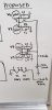
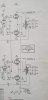
I want to split the 4 output tubes from the 12AX7 preamp tubes to allow me to individually bias each output tube (orignal Schematic of section attached)

1. Is my proposed wiring diagram correct and functional? Attached
2. I could use some help in determining the R values and wattage rating, and the C values.
I see some tube specs provide a rating for the resistor, there is none provided on this tube spec.
I assume I need to calculate it. I estimate is at 143 ohms. 21.5 vdc / .15 = 143 ohm for each R, correct?
I've researched and researched, but only confused myself by finding lots of contradictory information.
I would really appreciate some help determining the correct values and an explanation of the calcs, or a few links to some explanations you know to be accurate so I can learn.


Misc Notes:
I will have a separate transformer wired to provide regulated 24Vdc to 12AX7 heaters
I estimate that the 12AX7 tubes are providing 143.33 ohms total resistance
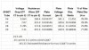
Resistance and voltage drop was measured from OT center tap to pin 3 of each 6v6GT
The amp is powered via a 117Vac bucking transformer at all times
This is a Harman Kardon A300 stereo tube amplifier from the 60's
The output tubes are 6V6GT EH. Spec sheet attached.

My specific BIAS readings are attached.
The output section of the schematic is attached.
My proposed design schematic is attached.
The datasheet for my output tubes is attached.

Thanks in advance
 

Attachments

  • 6v6eh tube spec datasheet.pdf
    6v6eh tube spec datasheet.pdf
    442.4 KB · Views: 10
  • Bias Readings.jpg
    Bias Readings.jpg
    62.9 KB · Views: 35
  • Orig A300 Schem.jpg
    Orig A300 Schem.jpg
    60.1 KB · Views: 37
  • proposed A300 Schem.jpg
    proposed A300 Schem.jpg
    55.8 KB · Views: 38
Register to hide this ad
honestly doing it that way doesn't offer any advantage over the stock system. Its not adjustable, and individual cathode resistors tend to degrade performance since the other tubes offer no regulation effect. You have them all tied together anyway, so no point in 4 resistors and 5 caps. Electrically this is just one resistor and one cap. A 12ax7 heater is basically 84 ohms, so expect about a 160 ohm resistor to sub for the pair.

If you really want individual resistors, you'd need 4x 160, or about 640 per-tube.

or just strap a pair of 12v zener diodes across the string to limit max heater voltage on the preamp tubes and run with it. At the end of the day performance will be pretty much identical with a lot less fuss. Also no need for extra transformers.
 
Aren't a lot of those amps biased like this? HK A500 (obviously), Fisher X-100-2...

Heard a couple of times that it was a cutting cost measure, not necessarily good. Like don't remove a 12AX7 when the amp is running... Your thoughts Gadget?

Patrice
 
Lots are made that way

Partly economy, partly genius I guess. Its a cheap way to get quiet DC heat on a phono tube without a more complicated power supply. The only big problem, and this is one that @dcgillespie pointed out and came up with the zener diode fix for, is that the current draw goes way up when the output power goes up. Basically meaning the voltage across those tube heaters climbs, and can get to the point where it abuses the tubes. The zeners will clamp that so it doesn't damage the 12ax7 heater.

pulling a 12ax7 won't really do any harm. It will just shut the output stage down since it has no cathode to ground connection. Voltages in the power supply will go up and if the caps can't handle it things might get unhappy but it won't damage the tubes or anything like that.
 
Ok, the resistor at the end of the string protect the tubes in a certain way (not perfect). Will look deeper into this thread.
 
Hi all, I need some advice and guidance.

I have an HK A300 stereo tube amp.
Presently the output tubes are biased throught the 12AX7 tubes
I want to split the 4 output tubes from the 12AX7 preamp tubes to allow me to individually bias each output tube (orignal Schematic of section attached)

1. Is my proposed wiring diagram correct and functional? Attached
2. I could use some help in determining the R values and wattage rating, and the C values.
I see some tube specs provide a rating for the resistor, there is none provided on this tube spec.
I assume I need to calculate it. I estimate is at 143 ohms. 21.5 vdc / .15 = 143 ohm for each R, correct?
I've researched and researched, but only confused myself by finding lots of contradictory information.
I would really appreciate some help determining the correct values and an explanation of the calcs, or a few links to some explanations you know to be accurate so I can learn.


Misc Notes:
I will have a separate transformer wired to provide regulated 24Vdc to 12AX7 heaters
I estimate that the 12AX7 tubes are providing 143.33 ohms total resistance
Resistance and voltage drop was measured from OT center tap to pin 3 of each 6v6GT
The amp is powered via a 117Vac bucking transformer at all times
This is a Harman Kardon A300 stereo tube amplifier from the 60's
The output tubes are 6V6GT EH. Spec sheet attached.

My specific BIAS readings are attached.
The output section of the schematic is attached.
My proposed design schematic is attached.
The datasheet for my output tubes is attached.

Thanks in advance
With Gadget's suggestion, here is what I initially did in my TA-5000X receiver.
First image is original configuration and second is modified.

index.php


index.php


Later I replaced filament bypass resistors with zeners per DG mod. Each tube cathode current is monitored and adjusted individually now.
 
I meant big resistor at the end of the heater string, not current sensing resistors. 330 ohms@3w in the case of the A500.
10ohm / 1w 2% connecting cathode string to ground? Current sensing resistor.
Per Dave's drawing, there's only one trimmer, so all grids get same bias voltage. This setup requires close matched quad of output tubes. Total combined current draw is measured across that 10ohm resistor. I think there is a "test point" label on Dave's drawing
 
Resistor(s) in parallel with heaters are for protection, yes. Those are replaced with zeners per Dave's mod
 
Resistor(s) in parallel with heaters are for protection, yes. Those are replaced with zeners per Dave's mod
Yes, I was wrong, sorry. In parallel, not series. I was inquiring at Gadget about those. I think you have the same sort of arrangement on the TA5000 schematic pictured above.

Dave Gillespie mentioned in his thread that it's far from perfect but better than nothing. Zener is the way to go but it's a bit over my head I must admit.

My Fisher has some kind of similar circuit with heater string.
 
Last edited:
Ok, 2.2k in parallel and 22 ohms before V1, V2 and V3 (12AX7's) in the case of the Fisher x-100-2. I remember having modified the 22 ohms value in mine to put heaters at different voltage. But now wondering if it's the cause of one of the Mullard 12AX7 dying about ten years ago?

I have to verify but I think I followed a suggestion on AudioAsylum to put heater at correct voltage. In retrospect, the original value had the effect of starving the 12AX7's, probably to compensate when current draw increased, thus not feeding them with too much heater voltage.

I'll have to verify what I've done. Old stock replacement 12AX7's are going ok 10 years later...
 
The T-5000x and the Fisher ones are slightly different because they tickle some of the cathode voltage back into the grid. Makes it easy to adjust the current through the tube, simply adjust how much voltage comes back to the grid. Fishers sometimes had a single pot from the factory to do that, or you can mod it for individual adjustment.

The A300 has the grids to ground through a resistor with no connection back to the cathode. You could in theory modify the A-300 to work like the Fishers and the T-5000 if you wanted to. It would need some extra resistance added to the total cathode circuit, and a resistor divider to tickle the grid voltage back in to make up for it. You'd end up losing some output power though since the cathode would be at a higher voltage vs ground, which means the plate to cathode voltage will be smaller. I suspect it would run into problems with low voltage through the tube heaters though, so it turns into a can of worms. Smart money is leaving it alone if the stock setup doesn't bake the tubes, and by OP's numbers it doesn't seem to do that. Just make sure you have a decently matched quad and life is good.

The zeners just act as a "clamp". You use one per tube heater, and all that it does is limit the voltage across the tube heater to whatever the zener voltage is. 12.1v zener means the tube heater is not going to see more than 12.1v. No idea what it could max out in stock form but its probably capable of going higher than 12.6v and thats not good for the tube heater. One thing about the stock Fisher and T-5000x though, they have a big fat shunt resistor that will help limit the max voltage the tube heater will see. The A300 (and my Fisher TA-600) doesn't have that, so the potential voltage swing is much greater. The only time you're likely to see the voltage get that high is pushing high output levels but its cheap insurance. I don't think you can mail a letter for what they cost.
 
The T-5000x and the Fisher ones are slightly different because they tickle some of the cathode voltage back into the grid. Makes it easy to adjust the current through the tube, simply adjust how much voltage comes back to the grid. Fishers sometimes had a single pot from the factory to do that, or you can mod it for individual adjustment.

The A300 has the grids to ground through a resistor with no connection back to the cathode. You could in theory modify the A-300 to work like the Fishers and the T-5000 if you wanted to. It would need some extra resistance added to the total cathode circuit, and a resistor divider to tickle the grid voltage back in to make up for it. You'd end up losing some output power though since the cathode would be at a higher voltage vs ground, which means the plate to cathode voltage will be smaller. I suspect it would run into problems with low voltage through the tube heaters though, so it turns into a can of worms. Smart money is leaving it alone if the stock setup doesn't bake the tubes, and by OP's numbers it doesn't seem to do that. Just make sure you have a decently matched quad and life is good.

The zeners just act as a "clamp". You use one per tube heater, and all that it does is limit the voltage across the tube heater to whatever the zener voltage is. 12.1v zener means the tube heater is not going to see more than 12.1v. No idea what it could max out in stock form but its probably capable of going higher than 12.6v and thats not good for the tube heater. The only time you're likely to see the voltage get that high is pushing high output levels but its cheap insurance. I don't think you can mail a letter for what they cost.
Amazingly, being a musician, it's better when I can look at a picture. I have a hard time figuring it with a schematic (how to layout the damn things!!).

Anyway, the A500 and the X-100-2 are seldom used at insane volume levels, max with volume at noon. Done it yesterday with the A500 as my son was listening music (big fat rap) at full blast in the shower. It was volume battle! The A500 didn't sound good at those levels anyway so I admit the defeat ;).

Thanks again for clarification, even if I'm too dumb to correctly figure the mod :)
 
You might get a slight bump in power output with the zeners, but probably not enough to matter.

I tend to work better from schematics, the signal flow is easier for me to "see". No idea what the inner construction on an A500 is, so no idea where would be easy to tie in a chain of diodes. Whenever I get around to re-capping my Fisher TA-600 I plan to add them though. I'll measure it to see how much difference it makes. I don't tend to listen at high volume so in reality its probably not needed but for how simple it is I don't see the harm in adding a bit of insurance.
 
or just strap a pair of 12v zener diodes across the string to limit max heater voltage on the preamp tubes and run with it. At the end of the day performance will be pretty much identical with a lot less fuss. Also no need for extra transformers.

This does not say that much to me as a beginner. I also read the thread linked by Patrice but that still did not make it 100% clear for me - if i read the diagram correctly,.the zener diodes are run parallel to the pre-amp tubes. Would it be possible to post the schematic with you mod penciled in?
 
Back
Top Bottom