• The move to the new server is done. There are some software and database maintenance updates in process. This has us passing the hat around to help out. We appreciate any donations. Seriously, even a dollar helps. The payment page may be found here - https://www.audiokarma.org/support.html

Harman Kardon A700 Red Plating

Rudiger

Know just enough to be dangerous
Subscriber
Hi Group,

I generally repair solid state gear so I'm not totally in the dark, but unfortunately for me, I have been asked to fix a Harman Kardon A700. When I received it the first time an e-cap in the power supply literally exploded. So I recapped the power supply and replaced the two diodes and ceramic caps. Someone else recapped it previously and all the film caps have been replaced. They didn't bother to get the right caps and just paralleled two caps to get a close uF. ie two .1 instead of a .25. Anyway, it also got two new JJ 7591's. It worked for about 2 weeks.

It was returned to me with a blown fuse. I had the power and driver tubes tested and 2 tested bad (one power tubes the JJ and a 7199 driver tube) all in the same channel. I find a 3.3 Ohm 5W resistor shorted in the power supply section. Maybe I missed it the first time? I replace it and am supplied with two new JJ tubes. That channel now red plates one of the tubes. The other channel has old rca 7591's that test good but like 70% on the tester. I replaced the coupling caps for the power tubes and driver tubes. Still red plates. I swapped channels with the power tubes. The old RCA don't appear to red plate. The JJ's seem fine in the other channel for the short time I had it on. ie minutes. This is when I hooked my scope up to it. I am seeing a small 60ish hz in the "bad" channel. The other has similar hz but even smaller amplitude. Is this causing my red plating issue? I'd assume I would see nothing on the scope like solid state, but I never hooked a scope to the output of a tube amp. All my testing is done hooked up to a pair of 8 ohm 200watt resistors if that matters.

I would assume power supply caps but they are less than a month old and its not the same amplitude signal in both channels. Tonight I intend to swap tubes all around and see what difference that shows me on the scope.

So the question is will this 60ish hz cause the red plating or should I be looking elsewhere?


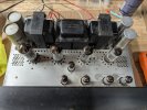
PXL_20250501_202456010.MP.jpg
 

Attachments

Register to hide this ad
pop all of the 7591 out and measure the voltage at pin 6 on each of their sockets. You want to make sure you have a reasonable bias supply voltage.

This does have a DC balance control, and if thats tweaked way too far over it might cause one tube to red plate. A bum balance pot would do it too so we need to make sure its got bias voltage to all 4 sockets first. Leaky coupling caps will screw this up too.

Assuming it does have reasonable voltage, this doesn't have a convenient means of monitoring current and setting it, so you basically get two options here

1) break the connection between pin 5 and ground and insert a small resistor to read voltage across. 1 or 10 ohms is the usual
2) set it for minimum hum in the output stage. This will make sure the current is equal on both tubes in that channel, but you won't have a clue how much current its actually drawing.

I'd probably go for the current monitoring resistors and further modify the bias supply so its adjustable per channel. Between a bias and a balance control you can actually set the output tubes where they belong. Modern tubes tend to not bias quite like the old ones too, so thats extra useful.
 
1) break the connection between pin 5 and ground and insert a small resistor to read voltage across. 1 or 10 ohms is the usual
^^^ This! Install a resistor in series with each cathode as a permanent modification. It's necessary for current measurements, just like the emitter resistors in a solid state amp. Just so you know, there have been significant problems in the past with the JJ 7591 tubes. It's very possible the issue you're seeing has nothing whatsoever to do with your work.

EDIT: You might also need to raise the bias voltage, maybe by reducing the value of the 120K resistors in each channel. Like @gadget73 said, the reissue tubes are not quite the equal of their predecessors.

Screen Shot 2025-05-01 at 5.09.37 PM.png

Jack
 
Last edited:
I'd probably try to not mess with the resistors tied to the grid, but I wouldn't have any problem messing with the 10k resistor between the rectifier and the feed out to the balance pots.
 
Alright here is what I got after installing a 10 ohm resistor on each socket.

Channel A -18.7 V on pin 6. Dc Balance pot measures 76.1k and 75k ohms on either half the pot. Across a 10 ohm resistor I get .652v and .669v.

Channel B -16.6V on pin 6. Dc balance pot measures 110.9k and 111.2k ohms on either half of the pot. Across a 10 ohm resistor I get .464v and .416v

Seems like these balance pots do not match.
 
I'd probably try to not mess with the resistors tied to the grid, but I wouldn't have any problem messing with the 10k resistor between the rectifier and the feed out to the balance pots.
The primary purpose of the 10K is CRC filtering. I don't think it will be very helpful to change its value, because it's driving a very high impedance in the form of the 200K balance pots and 120K resistors. That's why I suggested changing the 120K series resistors, which are loaded by the 270K grid resistors. The ratio just seem to be more effective.

Channel A -18.7 V on pin 6. Dc Balance pot measures 76.1k and 75k ohms on either half the pot. Across a 10 ohm resistor I get .652v and .669v.

Channel B -16.6V on pin 6. Dc balance pot measures 110.9k and 111.2k ohms on either half of the pot. Across a 10 ohm resistor I get .464v and .416v

Seems like these balance pots do not match.
I had that problem with my Citation V. I ended up adding a parallel resistor across the higher reading pot, then adjusting bias voltage to compensate for the overall lower pot values. Your measurements of 0.652V and .669V across the cathode resistors are way too high. You will need to increase the negative bias voltage.

Jack
 
So it sounds like on channel A I need to add around a 34k Ohm resistor between the pot and the 120k resistor on each side of the pot. That should make the resistance out of the pots even. Then the voltage should lower to the 16.6v or closer to the 17v the schematic says. Then I can retest the voltage drop across the resistors I added and see where the current is.
 
No, that's not right. One pot is about 150K total, the other is roughly 220K. If you install a 240K resistor on each side of the 220K pot, total resistance will be about 150K. This isn't a perfect solution, but it should keep the "bad" channel from over-dissipation.

Jack
 
It seems like the best solution would be 2 new pots since I would need to order the resistors anyway. I'll continue searching today but I haven't found anything suitable. What wattage is needed for this pot? Any leads to where suitable pots can be purchased? Digikey and mouser appear to only have smaller pcb style. Lots of out of stocks right now.
 
Looks like it needs to be more negative on channel A, which is interesting because its already more negative than the other channel by a fair bit. Those grid resistors may be off by a fair bit too. I'd probably at least measure all of those parts and measure the pot with it disconnected from the rest of the circuit. More likely I'd just change the resistors and know they are reasonably matched and on value.
 
It seems like the best solution would be 2 new pots since I would need to order the resistors anyway.
The older style pots can be difficult to source. If you do find something that's a good fit mechanically, it might be a different value. That would mean the other values around the pots will also need to change. eBay sometimes has NOS components, but 200K is an uncommon value. Another source for older pots is Surplus Sales of Nebraska.

Jack
 
I went ahead and ordered 2 of those pots and the some resistors. Once they arrive I'll be back with more info.
 
Without my notes in front of me I believe most voltages were high by around 15-20 volts. Like the power supply 410 was 430, 400 was 420 and so on. The two diodes off the red transformer wire were replaced. One was shorted.
 
I'm back with more data. New dc balance pots installed. Bias voltage is 17.1v on both channels now. The RCA tubes measured across the 10 ohm resistor is ~.340v. The JJ tubes measure ~.660-.700v. I swapped the tubes to the other channel and those measurements follow the tubes. The JJ tubes accelerate to those values quickly compared to the old RCA's.

What is the best course of action now? The JJ tubes will need resistance values changed to work? The RCA's measured 60 or 70% on the tube tester does that a play a role here? It appears this is a tube issue. I assume not all 7591's are the same specs. Please educate me on where to go from here.
 
In general, most new production tubes want a more negative bias supply to stay in the spec dissipation range than old production tubes. JJ 7591 tubes are also known not to be the brand's best tube. RCA tubes are probably on the weak side.
 
yeah bit of a mix of probably slightly tired old tubes and new tubes that bias weird. Its annoying but not a whole lot to be done for it besides making the thing adjustable.

extra annoying, this bias circuit is kind of stupid so making it adjustable will mean a balance pot of a very different value and making some other changes to the resistors to make it make sense. I need to get to bed but I'll see if I can scribble something up tomorrow that will get it done. Its going to end up needing 4 pots, probably all 10k or so, and possibly some further re-jiggering on the bias supply to get enough voltage to work with. Looks like it supplies -22 now which may not be enough. Should about another 15 volts available if a few parts get moved around though.
 
Looks like it supplies -22 now which may not be enough.
Schematic shows -32v out of the bias supply point. Should be plenty enough to implement IBBA or IBAM and eliminate the original 120k and balance pots.
R30/R34 will be disconnected from the ground and the new bias adjustment circuit connect to them as in this drawing it's connected to existing R117 - R120 in Fisher 400 receiver. The bias adjust circuit resistor values need to be adjusted so the mid-point of the trimmer results in desired negative voltage at the output tube grids.


1746617387109.png
 
Back
Top Bottom