• The move to the new server is done. There are some software and database maintenance updates in process. This has us passing the hat around to help out. We appreciate any donations. Seriously, even a dollar helps. The payment page may be found here - https://www.audiokarma.org/support.html

Harman Kardon Citation 22 - Remote Power On not working

puma1824

Member
Harman Kardon Citation 22 - Remote Power On not working.

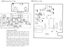
Any ideas why remote on wouldn't work? I measure the trigger output from the mini jack cable and it reads 12v when on and 0v when off but using it on the Citation 22 doesn't trigger to turn off or on. It remains on even if a cable is disconnected. I flipped the switched next to it to turn on the feature.

Thoughts?
citation22-remote.jpg
 
Register to hide this ad
The first thing I would do is flip the remote power on switch back and forth several dozen times and try it again. The switch could be oxidized, especially if it was in the off position for many years.
 
The first thing I would do is flip the remote power on switch back and forth several dozen times and try it again. The switch could be oxidized, especially if it was in the off position for many years.
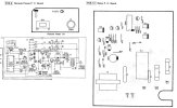
Thanks. Unfortunately that didn't work. I pulled out the switch assembly and tested each point for continuity and it's switching correctly when I flipped the switch. So at least at the switch board both the mini jack and the switch is working. I guess I should checkout the Relay PC Board nest. I'm new to all this so not quite sure to look for. What are the odds that IC201 is bad? Anything else I should check? Anyone know of a good substitute for the TC4027BP / IC201?

C22-Remote-schematic2.jpg
 

Attachments

  • C22-Remote-schematic.jpg
    C22-Remote-schematic.jpg
    79 KB · Views: 16
Last edited:
Do the standby leds light up when there is nothing plugged into the remote turn on jack? If they do then that tells us the transformer is sending power to the coil of the relay. The other side of the relay coil is grounded through Q204 so the next thing to check is to put power to the remote turn on jack. Then check to see if Q204 is receiving power to the base. There should be a small voltage at the base of Q204. If not then most likely the IC is bad.
 
Do the standby leds light up when there is nothing plugged into the remote turn on jack? If they do then that tells us the transformer is sending power to the coil of the relay. The other side of the relay coil is grounded through Q204 so the next thing to check is to put power to the remote turn on jack. Then check to see if Q204 is receiving power to the base. There should be a small voltage at the base of Q204. If not then most likely the IC is bad.
The standby LED does not light up when nothing is plugged into the remote turn on jack. The physical switch appears to be working correctly (tested continuity & voltage). Currently the amp acts as if I never togged the remote switch on as the amp remains powered on (never seen the standby led lite) and doesn't change state when remote wire is plugged in. Would I still check the relay they way you recommended or try something different knowing the standby LED does not light up when nothing is plugged into the remote turn on jack?
 
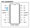
With nothing connected to the remote jack check voltage at pins 7, 4 and 1 of the IC.
Ok in the process of getting ready to try and read the voltage at the pins I accidentally bridged pins 2 & 3 which made the relay click to put the amp in a Remote Standby state, status LED lit and all. Proceeded to hook up the trigger wire which successfully turned on the amp but unfortunately either powering off the source the amp did not go back into Remote Standby. Disconnected the trigger cable, still on. Only way to get it back into Remote Standby is to short the pins again. Another thing sometimes if I have the cable plug in (with no voltage) or disconnected it will come out of standby and turn on. Does this mean the IC is bad or something else?

IC-schematic-TC4027BP.jpg
 
Last edited:
It does sound like the IC is acting flaky. I would try changing it if you can find a replacement. There is one on Ebay, but no guarantee if its real. But it's cheap enough that I would try it.
 
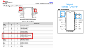
All of the pin functions are the same just the number of each flip-flop is different. Amplifier doesn't know 1 from 2 and vice versa.
 
So I was curious about what AI would think about all the data collected and observations and this is AI (in this case Gemini) had concluded below. Thoughts? Does AI logic seem right? Any corrections or other recommendations you (humans :) ) may have?

By the ways thanks everyone (humans :) here for their input!

AI Response:

Based on the schematic and the provided text description, here is a more detailed and accurate rewrite of the interaction between pins 1, 2, 4, 7, and 16 of the IC201 (TC4027). The text clarifies the role of pins 4 and 7 as the RESET and SET inputs, respectively, and pins 1 and 2 as the Q and Qˉ outputs.

Pin Interactions in the Remote Power ON/OFF Circuit


The IC201 (TC4027) is a dual J-K flip-flop. The remote power ON/OFF functionality is controlled by one of the flip-flops, which uses pins 1, 2, 4, and 7.
  • Pin 16 (VDD) and Pin 7 (VSS) provide the power supply for the IC. Pin 16 is the positive supply voltage (VDD), and Pin 7 is the ground connection (VSS). The text, however, refers to "7 pin (SET)" and "4 pin (RESET)". This suggests a conflict or a slightly different pinout usage. For a TC4027, pin 7 is typically VSS. The text description seems to be referring to the J-K flip-flop's internal pins rather than the IC's physical pin numbers. A closer look at the circuit shows Pin 7 is connected to ground, making it the VSS pin. It is likely the text's reference to "7 pin (SET)" is an error or refers to a different IC. I will proceed with the assumption that the text is referring to the functions SET and RESET, which are connected to some pins of the IC, and the schematic's physical pin numbers are what's important.
Let's re-evaluate the interaction based on the schematic's physical pins and the text's functional description. The provided text is a description of a single J-K flip-flop's behavior. Let's assume the text meant "the SET input pin" and "the RESET input pin" are controlled by the remote power switch.

Corrected Interaction Based on Schematic and Text:
  • Pin 16 (VDD) and Pin 7 (GND/VSS) provide power to the IC.
  • Pin 4 (RESET) and Pin 7 (SET): The description states that the remote power switch input controls the levels of the SET and RESET pins.
    • Stand-by Mode (Remote Power LOW): The text states a LOW level on the remote power input results in a HIGH level at the SET pin and a LOW level at the RESET pin. The schematic shows a connection from the remote power circuit to pins 4 and a circuit that drives the SET input.
    • Power ON Mode (Remote Power HIGH): The text states a HIGH level on the remote power input causes the SET pin to become LOW and the RESET pin to become HIGH. This toggles the state of the flip-flop.
  • Pin 1 (Q) and Pin 2 ( Qˉ ): These are the complementary outputs of the J-K flip-flop.
    • Stand-by Mode: When the SET input is HIGH and RESET is LOW, the flip-flop is in a "set" state. The text says this makes the level of pin 1 (Q) HIGH.
    • Power ON Mode: When the state of the SET and RESET pins reverses, the flip-flop's output changes. This makes the level of pin 1 (Q) LOW and the level of pin 2 (Qˉ) HIGH.
  • Interaction with the Transistors and LEDs:
    • Stand-by Mode (Pin 1 HIGH): The HIGH level on pin 1 (Q) turns ON transistor Q202. This causes LEDs D204 and D205 to light up, likely indicating the stand-by state.
    • Power ON Mode (Pin 1 LOW, Pin 2 HIGH): The LOW level on pin 1 turns OFF Q202, causing the LEDs to turn OFF. The HIGH level on pin 2 ( Qˉ ) turns ON transistor Q204, which operates a relay (implied by the description) to supply power to the amplifiers.
Summary of the Interaction:
The IC201, a J-K flip-flop, acts as the memory element for the remote power switch. The remote power input controls the SET and RESET inputs (likely pins 4 and a pin connected to the SET function) of the IC. The state of the flip-flop determines the logic levels of its outputs, Pin 1 (Q) and Pin 2 (Qˉ).
  • Pin 1 (Q) controls the stand-by indicator: A HIGH on Pin 1 turns on Q202, which illuminates the LEDs.
  • Pin 2 ( Qˉ ) controls the main power relay: A HIGH on Pin 2 turns on Q204, which activates a relay to supply power to the main circuit.
The IC's power is supplied by Pin 16 (VDD) and Pin 7 (GND). The overall circuit uses the flip-flop to translate a simple toggle switch action (remote power button) into two distinct and complementary output states, one for stand-by and one for full operation.

 
So I replace the IC with a new one. When I first powered it on the amp was in stand-by mode as expected. Then turned on when I the remote device powered on. Up to that point all was good but then when I shut down the remote device the amp did not go back into stand by. Does it take some time after the remote turns off to power down the amp? The only way I got it to go back to standby was to shut off the amp and unplug from power. Then when plugged back in and powered on it was back on standby.

Thoughts on what else it could be? Would bad cap or other component prevent it from going back into stand by? Is there a delay when the remote is turned off until the amp goes back into stand by?

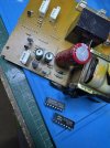
IMG_1045.jpeg
 
Did you ever check the output voltage regulator, emitter of Q203? Check it and then check the voltage across D203, 9V? Just making sure the power supply isn't killing the flip-flop.
 
Did you ever check the output voltage regulator, emitter of Q203? Check it and then check the voltage across D203, 9V? Just making sure the power supply isn't killing the flip-flop.
I have not. I'm a little new to all this and I'm trying to figure out where the output voltage of Q203 & D203 so I can measure it.
 
To measure D203, the orange glass looking diode, put your meter on each end and measure the voltage. From the Zener part # it looks to be 9ish volts. To measure the emitter voltage of Q203 pin 16 of the flip-flop should do, reference ground.
 
To measure D203, the orange glass looking diode, put your meter on each end and measure the voltage. From the Zener part # it looks to be 9ish volts. To measure the emitter voltage of Q203 pin 16 of the flip-flop should do, reference ground.
Looks like D203 is ~9.2v and Q203 (pin 16) ~8.6v, pin1 ~8v, pin4 ~0v when in standby. When amp on (not on standby) pin1 ~0.1v and pin4 ~9.3v (Remote on) then when remote off pin1 still ~0.1v and pin4 ~0v. For whatever reason pin1 is not going back high.
 
Last edited:
Pin 16 should be hot no matter what IF the amp is plugged in. It's the regulated voltage that runs to whole circuit, if no voltage nothing will work.
 
Pin 16 should be hot no matter what IF the amp is plugged in. It's the regulated voltage that runs to whole circuit, if no voltage nothing will work.

OOOOOOH WAIT Pin 16 I didn't measure I was measing pin8 duh....one sec brb after checking

My mistake pin 16 is ~8.6v all the time
 
Last edited:
Back
Top Bottom