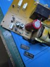
So I was curious about what AI would think about all the data collected and observations and this is AI (in this case Gemini) had concluded below. Thoughts? Does AI logic seem right? Any corrections or other recommendations you (humans

) may have?
By the ways thanks everyone (humans
here for their input!
AI Response:
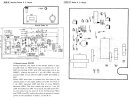
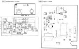
Based on the schematic and the provided text description, here is a more detailed and accurate rewrite of the interaction between pins 1, 2, 4, 7, and 16 of the IC201 (TC4027). The text clarifies the role of pins 4 and 7 as the RESET and SET inputs, respectively, and pins 1 and 2 as the Q and Qˉ outputs.
Pin Interactions in the Remote Power ON/OFF Circuit
The IC201 (TC4027) is a dual J-K flip-flop. The remote power ON/OFF functionality is controlled by one of the flip-flops, which uses pins 1, 2, 4, and 7.
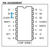
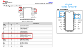
- Pin 16 (VDD) and Pin 7 (VSS) provide the power supply for the IC. Pin 16 is the positive supply voltage (VDD), and Pin 7 is the ground connection (VSS). The text, however, refers to "7 pin (SET)" and "4 pin (RESET)". This suggests a conflict or a slightly different pinout usage. For a TC4027, pin 7 is typically VSS. The text description seems to be referring to the J-K flip-flop's internal pins rather than the IC's physical pin numbers. A closer look at the circuit shows Pin 7 is connected to ground, making it the VSS pin. It is likely the text's reference to "7 pin (SET)" is an error or refers to a different IC. I will proceed with the assumption that the text is referring to the functions SET and RESET, which are connected to some pins of the IC, and the schematic's physical pin numbers are what's important.
Let's re-evaluate the interaction based on the schematic's physical pins and the text's functional description. The provided text is a description of a single J-K flip-flop's behavior. Let's assume the text meant "the SET input pin" and "the RESET input pin" are controlled by the remote power switch.
Corrected Interaction Based on Schematic and Text:
- Pin 16 (VDD) and Pin 7 (GND/VSS) provide power to the IC.
- Pin 4 (RESET) and Pin 7 (SET): The description states that the remote power switch input controls the levels of the SET and RESET pins.
- Stand-by Mode (Remote Power LOW): The text states a LOW level on the remote power input results in a HIGH level at the SET pin and a LOW level at the RESET pin. The schematic shows a connection from the remote power circuit to pins 4 and a circuit that drives the SET input.
- Power ON Mode (Remote Power HIGH): The text states a HIGH level on the remote power input causes the SET pin to become LOW and the RESET pin to become HIGH. This toggles the state of the flip-flop.
- Pin 1 (Q) and Pin 2 ( Qˉ ): These are the complementary outputs of the J-K flip-flop.
- Stand-by Mode: When the SET input is HIGH and RESET is LOW, the flip-flop is in a "set" state. The text says this makes the level of pin 1 (Q) HIGH.
- Power ON Mode: When the state of the SET and RESET pins reverses, the flip-flop's output changes. This makes the level of pin 1 (Q) LOW and the level of pin 2 (Qˉ) HIGH.
- Interaction with the Transistors and LEDs:
- Stand-by Mode (Pin 1 HIGH): The HIGH level on pin 1 (Q) turns ON transistor Q202. This causes LEDs D204 and D205 to light up, likely indicating the stand-by state.
- Power ON Mode (Pin 1 LOW, Pin 2 HIGH): The LOW level on pin 1 turns OFF Q202, causing the LEDs to turn OFF. The HIGH level on pin 2 ( Qˉ ) turns ON transistor Q204, which operates a relay (implied by the description) to supply power to the amplifiers.
Summary of the Interaction:
The IC201, a J-K flip-flop, acts as the memory element for the remote power switch. The remote power input controls the SET and RESET inputs (likely pins 4 and a pin connected to the SET function) of the IC. The state of the flip-flop determines the logic levels of its outputs, Pin 1 (Q) and Pin 2 (Qˉ).
- Pin 1 (Q) controls the stand-by indicator: A HIGH on Pin 1 turns on Q202, which illuminates the LEDs.
- Pin 2 ( Qˉ ) controls the main power relay: A HIGH on Pin 2 turns on Q204, which activates a relay to supply power to the main circuit.
The IC's power is supplied by Pin 16 (VDD) and Pin 7 (GND). The overall circuit uses the flip-flop to translate a simple toggle switch action (remote power button) into two distinct and complementary output states, one for stand-by and one for full operation.