• The move to the new server is done. There are some software and database maintenance updates in process. This has us passing the hat around to help out. We appreciate any donations. Seriously, even a dollar helps. The payment page may be found here - https://www.audiokarma.org/support.html

Harman Kardon HK590i restoration

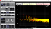
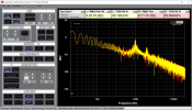
Got a new toy / piece of test equipment. A QuantAsylum QA403 audio analyzer. Been learning how to use it on the HK590i. Here are a few screenshots. Looks like it's performing up to specs. The high freq roll off in the last pic might just be me not knowing how to use it yet. Still working on that. Wish I could have tested it before working on it but next project I will. Still need to figure out how to test the RIAA curve on the phono input.
View attachment 3135556View attachment 3135557View attachment 3135558
i've been considering getting one of those. they look pretty neat but i would hate leaving my hp 8903b just sitting there unused.
 
i've been considering getting one of those. they look pretty neat but i would hate leaving my hp 8903b just sitting there unused.
If I had an HP 8903b I'd be happy with it. But after looking out for a deal on one and coming up dry for a while, I just bit the bullet. After only a couple hours of messing with it, I'd say it's fairly easy to use. Probably a little slower since it's entirely FFT. But the automated tests are pretty cool. You can just start one, leave and get some coffee and let it run.
 
If I had an HP 8903b I'd be happy with it. But after looking out for a deal on one and coming up dry for a while, I just bit the bullet. After only a couple hours of messing with it, I'd say it's fairly easy to use. Probably a little slower since it's entirely FFT. But the automated tests are pretty cool. You can just start one, leave and get some coffee and let it run.
well the 8903b doesn't do bode plots, neither does my scope(i'm one model number down from capable unit :(. that's the one thing i am lacking on that i wish i could do.
 
Figured out how to run the bode plot with RIAA EQ. They made that pretty easy. However, I don't think I'll get a valid run until I chase this down. Nice that the QA403 is confirming what I heard with my ears. There's a lot of power supply hum in the phono stage. Bad to the point that it swamps out the signal if you turn the volume up past about 3. So I guess I have some work to do.
phono input 60Hz hum.pngPhono input with correct input level.png
 
Well I found a problem in the power section of the phono board. Bad solder joint on the negative supply zener so fixed that but it didn't fix my problem. May have overvolted some stuff in there. I was hoping since it was only sending -31V downstream instead of -20 it didn't do much damage but kinda looks like it did. The power supply looks ok now. I do see some hum coming in on the power inputs using the scope but it's getting filtered before it leaves the power section. I started checking transistors in circuit but they all look suspect so gonna have to pull some. There are a lot of transistors in there. At least the board is easy to get to.
 
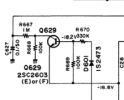
After sleeping on it, since this problem is affecting both channels equally, I want to be really sure it's not something in the power supply section of the phono board. There's this one section I don't understand too well so I need to figure out what it does. That diode takes a feed from the amp board and the output of this section feeds the gates of MOSFETs at the output of each channel of the phono stage. The voltages look ok according to the SM but it looks like the MOSFET influences negative feedback so I'm going to mess around with this section a little.
1709477855216.png
 
Last edited:
I wouldn't say I completely understand that part of the circuit yet but couldn't find anything really weird going on. Then thought, "Why am I being dumb? Why not just trace a signal through the phono stage?" Well, it looks fine. It's putting out a nice looking sine wave with good line level. Since the pre-amp works fine with the aux input, now I just have to figure out where it's going wrong in between. Looks like switches are my most likely problems. I cleaned them but didn't really verify they were good.
 
Well, scratch that theory too. Should have tried that phono board test while messing with the volume. When I turn it up to about 3, the main power supply starts to oscillate. It's taking a while but I think I'm getting somewhere.
 
After a bit of messing around with it to figure out exactly what's making this happen, it seems fine on aux input. But using the phono input with a 5 or 10mV 1kHz input signal, if I turn the volume up to 3 the ripple in the power supply jumps way up. Like to a couple volts of ripple and it goes up fast from there too if I turn the volume up a little higher. Oscillating probably wasn't the right word. Seems like it's just letting through a lot of 60Hz, and maybe harmonics of that. It's hard to check regulator diodes in circuit but I'm guessing those might be the culprits? The filter caps are new.
 
it seems fine on aux input. But using the phono input with a 5 or 10mV 1kHz input signal, if I turn the volume up to 3 the ripple in the power supply jumps way up.

unplug everything else from the unit and test again. same or does it stop?
 
unplug everything else from the unit and test again. same or does it stop?
Well, it is ok until I put the signal into the phono input and turn up the volume. It seems ok with phono selected but no signal going in. But once it starts I can turn the signal off and it still does it. Maybe heat related? I guess I could try heating the diodes a bit with no signal and see if that makes them act up?

I was thinking about how it could be the phono stage causing this but I just don't see how it would make the main power supply ripple jump like that. Even if it had a short somewhere I'd expect it to blow a fuse or something but not to just make the main supply start passing tons of low frequency noise.
 
Last edited:
But using the phono input with a 5 or 10mV 1kHz input signal
service manual specs at 2.2mv useable sensitivity on phono.

can you lower the signal level, maybe clip some probes on the back of the phono inputs on the receiver and set the level at 2.2mv and see if it still does it?
 
Thanks @painttoad I didn't see that in the SM. Didn't make a difference. Tried unhooking everything from the back and the ripple is about 100mV RMS and goes up to about 400mV RMS at full volume on one of the regulators (it has one for each channel and the phono stage just pulls from one of them), and about 250mV on the other. Seems maybe a little high? Then I tried hooking the dummy loads and scope to the speaker outputs and I'm seeing 60Hz ripple on the speaker outputs too. I don't see the ripple on the speaker outputs with Aux selected. Still can't get my head around how the phono stage is affecting the main power supply this much and getting so much 60Hz in it.
 
I did some more researching and that earlier snip of the power section of the phono board that feeds a couple MOSFETs at the output might be a ripple filter. I have no idea if it's working correctly, or if I'm right about it being a ripple filter.
 
I decided to do a quick check today and see if I can verify the test setup works with a different stereo so I hooked up my Sansui AU-555. It does the exact same thing. Looks great with the aux input. On the phono, the low freq noise goes through the roof when you turn the volume up. So I guess it's actually something to do with the test gear or setup. I've already moved the QA403 as far as possible away from everything and kept the cables as far away as you can when they're connected but it didn't change anything. I'll have to do some more playing around with it. But for now, I'll assume the 590i is probably working ok.
 
Did some more work trying to figure out how to get a test setup that works. I was able to duplicate the behavior with my signal generator and scope so it's not just a QA403 problem.

With dummy loads and scope hooked up but nothing hooked up to the input jacks everything behaves well. Full volume and just a little more noise showing on the scope.

With cables plugged into the input jacks but the other ends not connected to anything I see some high frequency noise. The scope's freq counter shows it in the MHz but it's still fairly low amplitude. Still don't see the power supply issue. After doing some research, I think you'd call this motorboating, where the power supply starts to oscillate?

Hooking up the cables to the signal generator, even with the signal turned off I start getting the power supply problem. So I'm leaning towards a ground issue as my problem. I'm not sure but maybe using single ended connections is my problem here. My signal generator and the QA403 can do differential so I'm going to try that I think. Need more cables, probes and adaptors to do it though. Maybe a USB isolator too?
 
Did some more work trying to figure out how to get a test setup that works. I was able to duplicate the behavior with my signal generator and scope so it's not just a QA403 problem.

With dummy loads and scope hooked up but nothing hooked up to the input jacks everything behaves well. Full volume and just a little more noise showing on the scope.

With cables plugged into the input jacks but the other ends not connected to anything I see some high frequency noise. The scope's freq counter shows it in the MHz but it's still fairly low amplitude. Still don't see the power supply issue. After doing some research, I think you'd call this motorboating, where the power supply starts to oscillate?

Hooking up the cables to the signal generator, even with the signal turned off I start getting the power supply problem. So I'm leaning towards a ground issue as my problem. I'm not sure but maybe using single ended connections is my problem here. My signal generator and the QA403 can do differential so I'm going to try that I think. Need more cables, probes and adaptors to do it though. Maybe a USB isolator too?
did you try flipping ac plugs 180degrees in outlets one at a time?
 
did you try flipping ac plugs 180degrees in outlets one at a time?
I did on the stereo and made sure the stereo neutral was plugged into wall neutral even though the plug isn't polarized. That was the first thing I did. The signal generator and scope have grounded plugs though (which could be part of my issue?). The QA403 is USB powered so can't really flip that.

I think I'm going to make up a set of differential cables and float the ground on the signal generator to see if that helps but had to order some stuff to make them.
 
I've been pretty busy with moving and getting settled in a new place. Just getting around to setting up some of my test gear. I never got around to testing the phono stage on this 590i very well so here are some graphs from the QA403. I'm using the setup they suggested to me on the QuantAsylum forums, which is to just use a tape record out jack to test the phono stage and it does seem to work that way.

Anyway, here are some test results.

Freq response from 3mV to 8mV input-
HK 590i phono stage freq response.png

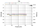
THD vs Freq-
HK 590i phono stage THD vs. freq.png

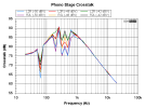
Crosstalk-
HK 590i phono stage crosstalk.png
 
One thing I'll note for anyone who decides to tackle one of these in the future. Cleaning the dirty pots and switches requires quite a bit of disassembly. The pots are buried under a couple other boards that have to be moved to get at them and the front panels have to be removed. The tone and balance pots needed to be desoldered from the board to blast them out well enough. The switches are easy enough to clean by squirting some DeOxit in the holes on top or into the gaps on the front side. I didn't need to desolder or disassemble the switches at all.

Also, there's quite a bit of circuit board glue used and on mine it was turning dark and getting brittle. I don't think it was really causing any problems yet but probably would have turned conductive and corrosive soon. All that was removed with acetone, q-tips, and a screwdriver. Combined with how much disassembly I had to do, I decided to recap it while I was in there. All my caps seemed to be electrically fine and not leaking but lots of them had glue on them so it was easier to replace them than try to clean all that off. Those caps are 40 years old and I don't want to go through the disassembly again in a couple years if I can avoid it by just replacing the caps while I'm in there now. The only board I didn't recap was the logic control board. It's on top, is pretty easy to remove, and didn't have any glue on it so I figured it's easy enough to do in a few years if it's needed then.

Do you have any photos of the pots and getting to them? Or of the glue you had to remove? Might help others who use this as a guide later.
 
Back
Top Bottom