• The move to the new server is done. There are some software and database maintenance updates in process. This has us passing the hat around to help out. We appreciate any donations. Seriously, even a dollar helps. The payment page may be found here - https://www.audiokarma.org/support.html

Heathkit A9-xx chassis

So, the input to the gas tube needs to be the same as the output? Example,,, OD3 output is 153VDC, so it needs a resistor to bring B+ down to 153V ?

The gas tubes on the RCA amp have an .047 around them...

Does the gas tube need a load on it to experiment with? don't want to blow one, or have it run away, experimenting with it!!!

Thanks for the input...
Regards,
John
 
Post #18 pretty much says what you need to do.

Putting some rough numbers to it as an example:

If you use two VR105s in series that will give you 210V for the screens. (Using two regulator tubes of the same type is nice since they both have the same characteristics)

If I extrapolate the 6L6 data sheet values, it looks like at the operating conditions you will be running the tube (330V plate, 210V screens), the idle screen current is 2.5mA and the max signal screen current is about 5 mA. So let's design around a max screen current of 5mA. If this is a stereo chassis build, two 6L6 tubes will draw a max of 10 mA screen current at max signal conditions.

The VR105 data sheet says it can regulate with anywhere from 5mA to 40mA running through the tube. So let's give ourselves a little buffer and shoot for no less than 7.5 mA current running through the VR105s at max signal screen conditions.

Thus, at max signal conditions, 7.5 mA will be running through the regulator tubes, and 10 mA will be consumed by the screens (both channels), therefore the power supply needs to supply 17.5 mA total, at max signal conditions.

So the series resistor as discussed in post #18 will need to be sized to drop 330V-210V = 120V at 17.5 mA. So the resistor will need to be 120V/17.5mA = 6.8K. The heat dissipated in this resistor will be 120V*17.5mA = 2.1 watts. So a 10 watt wirewound I would say would be minimum. (the resistor will get hot, so mount it somewhere in the chassis where it won't heat up other critical parts too much).

If you will be running only a single channel with the screen regulator, then the current demands would drop to 7.5mA + 5 mA = 12.5 mA (at max signal conditions), and the resistor would need to be about 120V/12.5mA = 9.6K, and 10K will be close enough. In this case it will dissipate 1.5 watts of heat, so I'd still go with a 10 watt wirewound.
 
Thanks for spelling it out, saw the examples in the RCA manual, my RCA amp, and the example Gadget posted, but couldn't figure out how to use just one tube....
The math you provided confirms that I can't... This will be a stereo amp, usually just build one channel at a time, to see how it works/sounds...
I wanted to use the regulator, to fill the chassis hole, I have them, and they're really cool!

It seems there's no way around just using one, so, I may have to rethink the plan, I'm still stuck with one hole, dead center, the only single tube would be the rectifier, or put a can there, but its not where either should go...

Maybe rethink the chassis choices,
Thanks for the info, we'll get it...

Regards,
John
 
Ah, no problemo--if you don't mind substituting a Zener for one of the gas tubes.

Apply the principal to obtain whatever screen voltage you really want, but I'd try to keep the Zener as small in value as possible to keep the heat dissipation through it as low as possible. For example, let's say you used a VR-105 plus two 51V Zeners (all in series), to give you a 207V regulated screen voltage.

Using the same parameters in the example and method of calculation as previously discussed, the series resistor would be about 7K, and 6.8K will be close enough. At no signal (which would be the max dissipation case for the zeners) each of the Zener's would dissipate about 51V*12.5mA = ~0.64W, so I'd go with 5W Zeners for more thermal headroom, and mount them someplace under the hood where they will pick up minimal heat from the surroundings.
 
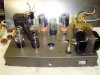
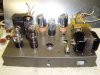
Any opinions on chassis layout? The tx are just for size and position... Second and 3rd pic are with G or GB rectifier...
Still contemplating the gas regulators...this may get too complected for a novice like me, but, I like to use stuff that's I already have!!

Regards,
John
 

Attachments

  • P4010009.jpg
    P4010009.jpg
    76.4 KB · Views: 16
  • P4010010.jpg
    P4010010.jpg
    87.2 KB · Views: 14
  • P4010011.jpg
    P4010011.jpg
    88.8 KB · Views: 14
Didn't see this post... Zeners, huh?? Never used them, but I'm only here to learn!!! I've used bridges for DC on heater supplies, but that's about as much sand I've put into a tube amp...
Seems like a cheaper solution...Have to look into them ...

Thanks for the info,

Regards,
John
 
You still need the resistors in the chain. Output of the regulator tube is relatively clean, but it needs about an 0.1uf across it to filter out any hash generated internally.

Hows this look? The original circuit for the screens is in the circles,,, seems they need to be removed to use regulator tubes...

Not sure what was meant by "resistors in the chain",,, is the .1 cap around the tubes OK...

I appreciate the input...

Regards,
John
 

Attachments

  • P4020004.jpg
    P4020004.jpg
    39 KB · Views: 19
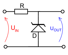
A zener diode is the modern equivalent of a gas regulator tube. Wires in exactly the same way, does pretty much the same job. its just a small blob of glass instead of a glowing bottle of gas.

220px-Zener_diode_voltage_regulator.svg.png


Looks about right, though the plates of the 6L6 go to the output transformer and all that. The dotted stuff in circles can go away since thats how it would have been done without a fixed regulator.


Regarding the connections on 3 and 7, the way I've seen that used before is the 6.8k might come into pin 3. Pin 7 would then be connected to pin 5. That will keep the screens from going to full B+ if the regulator tube is removed. They will go to open circuit instead.

You can wire it straight off the output of the main rectifier tube if you wanted though. That would kill all of the B+ in the chain so nothing got any voltage if the tube was removed. Mostly its a safety sort of deal to make sure that removing a tube will not cause a high voltage condition somewhere down the line.
 
One note: because of potential variations in tube characteristics from the bogey values listed on the 6L6 data sheet, actual size of the 6.8K resistor could need to be a bit smaller, maybe even as small as 4.7K.

When you get to the testing stage, if you put a 100 ohm resistor in series with each screen, then you can measure the voltage drop across it at idle. If it's more than about 0.25V, that means the screens are drawing more than was designed for (0.25mA), and in that case you should reduce the size of the 6.8K resistor.

Probably the best approach is to purchase a few different sizes between 4.7K and 6.8K. You don't want this resistor too small or too large. Too small and it will shunt unnecessarily large amounts of current through the gas tubes as well as create excessive heat from the resistor itself. But too large and the amp will go in and out of regulation while program material is playing, or not even regulate at all. Somewhere between 6.8K and 4.7K should be about right.
 
Looks about right, though the plates of the 6L6 go to the output transformer and all that. The dotted stuff in circles can go away since thats how it would have been done without a fixed regulator.


Regarding the connections on 3 and 7, the way I've seen that used before is the 6.8k might come into pin 3. Pin 7 would then be connected to pin 5. That will keep the screens from going to full B+ if the regulator tube is removed. They will go to open circuit instead.

You can wire it straight off the output of the main rectifier tube if you wanted though. That would kill all of the B+ in the chain so nothing got any voltage if the tube was removed. Mostly its a safety sort of deal to make sure that removing a tube will not cause a high voltage condition somewhere down the line.

Thanks for the explanation...
I don't know how much current the jumper can handle thru the tube, RCA manual doesn't say,,, using it to just break screen ckt sounds like a winner... The RCA PA amp uses it to disconnect teh primary of teh B+ trans, so it should handle B+ on this amp easily, I'll probably have separate filament and plate tx, as I don't have one big enough...

Thanks for clearing up "needing the resistors in the chain".... It really threw me off, I couldn't figure using the gas tubes and the screen ckt at the same time!!

I just drew the screen ckt... already have most of the amp built on a board, waiting on a couple of caps from Mouser,, and then gotta finish teh PS...

Regards,
John
 
Last edited:
I whacked together an AM transmitter and used a gas regulator on the plate, mostly because I had it. It was built on an old chassis with this massive wirewound on it that had an adjustable tap. I initially had the tap set to too much resistance and you could watch the regulator tube pulse in and out at times with variable current draw or even line voltage fluctuations. A bit lower value to keep the tube conducting enough for stable regulation fixed it.
 
One note: because of potential variations in tube characteristics from the bogey values listed on the 6L6 data sheet, actual size of the 6.8K resistor could need to be a bit smaller, maybe even as small as 4.7K.

When you get to the testing stage, if you put a 100 ohm resistor in series with each screen, then you can measure the voltage drop across it at idle. If it's more than about 0.25V, that means the screens are drawing more than was designed for (0.25mA), and in that case you should reduce the size of the 6.8K resistor.

Probably the best approach is to purchase a few different sizes between 4.7K and 6.8K. You don't want this resistor too small or too large. Too small and it will shunt unnecessarily large amounts of current through the gas tubes as well as create excessive heat from the resistor itself. But too large and the amp will go in and out of regulation while program material is playing, or not even regulate at all. Somewhere between 6.8K and 4.7K should be about right.

I know some Ohms law, but, never seem to get the the right figures to put in the formula off teh data sheets...More used to using Amps, Volts and Watts... The fractions and decimal points stump me sometimes... Someone said its easier to measure than compute, and that's what I do most of the time, never be an engineer, I guess,,, Glad you guys can do it!!

I put in a Mouser order yesterday, and tried to amend it for the 6.8K, and 10k resistors,,, I'll call em this morning, and see if I can add some more to experiment with the regulators...


Appreciate your ongoing help,,,
Regards,
John
 
Last edited:
Any opinions on chassis layout? The tx are just for size and position... Second and 3rd pic are with G or GB rectifier...
Still contemplating the gas regulators...this may get too complected for a novice like me, but, I like to use stuff that's I already have!!

Regards,
John

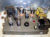
Thought you guys liked pics!! No votes on which chassis or layout to use?
Here's what I think will work the best, with what I have, and ties in with teh thread title!! The PS is in its planning stage!

Regards,
John
 

Attachments

  • P4020005.jpg
    P4020005.jpg
    97.1 KB · Views: 17
  • P4020008.jpg
    P4020008.jpg
    113.6 KB · Views: 13
I whacked together an AM transmitter and used a gas regulator on the plate, mostly because I had it. It was built on an old chassis with this massive wirewound on it that had an adjustable tap. I initially had the tap set to too much resistance and you could watch the regulator tube pulse in and out at times with variable current draw or even line voltage fluctuations. A bit lower value to keep the tube conducting enough for stable regulation fixed it.

Yep,,, I have some big adjustable WWs,,, may be good to use setting up the PS,,,
Thanks for the thought...

Regards,
John
 
Gas tube regulators require 5ma thru the tube itself. Buffer in 5 ma for potential line voltage drop. Add the 10ma tube peak current draw + 10ma for 20ma total.

Resistor value is calculated by applied voltage minus the tube operating voltage divided by the current draw.

Example- 400 volts - 210 volts = 180 volts. 180 volts/.020 amps = 9000 ohm.

Most simply calculate the regulator tube current draw at maximum current. Miniature regulator tubes are rated at 35 ma current draw and octal base are rated at 40ma current draw.

Example- 180 volts/.035 = 5142 or use 5200 ohms.
 
Thanks for the example,,, I can just substitute my readings to your formula,,,
Think I'm catching on slowly...

Regards,
John
 
Update .... Just called Mouser, the order is already processed, couldn't add the resistors... Maybe find a few locally, but not likely... Was on a roll here, seems I hit a wall!!! This is where my only engineering skills come in to play,,, make it work with what you got!!!!!

Regards,
John
 
Try it with what you ordered. May be fine.

If the gas tube pulses or does not light, add in parallel to the 6.8K resistor anything you've got in the neighborhood of 20K to 30K ohms (3 watt or larger). That will bring the total resistance down a bit and should address it, if it happens at all.
 
I just tacked together a test board with two 0C3 in series, 6.22K resistance, and a .1 cap across the tubes... Just thinking, I need the screen load to try this out, correct? If so, gotta wait for the rest of the caps to get here, to finish the test amp chassis... Can I use resistors or a choke or something to take the place of the screen load, to test teh gas tube ckt?

I didn't get any of the resistors for the regulators on the order... Seems its an automated system, and they couldn't add any of them... I'll work out something, if I can get it close...

Regards,
John
 
Try it with what you ordered. May be fine.

If the gas tube pulses or does not light, add in parallel to the 6.8K resistor anything you've got in the neighborhood of 20K to 30K ohms (3 watt or larger). That will bring the total resistance down a bit and should address it, if it happens at all.

UPDATE: Mouser order...
The CS rep just emailed me to say they started another order, with 4 more resistors, between 4.7K - 10K... they are shipping it at no charge,,,, Can't get better service then that!!!!!! Should have all I need by the end of teh week...

Regards,
John
 
Back
Top Bottom