• The move to the new server is done. There are some software and database maintenance updates in process. This has us passing the hat around to help out. We appreciate any donations. Seriously, even a dollar helps. The payment page may be found here - https://www.audiokarma.org/support.html

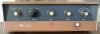
Heathkit AA-151 restoration in-progress

thorpej

AK Subscriber
Subscriber
[Post was stuck in limbo during the outage...]

I'm whipping the Heathkit AA-151 that I picked up a while ago back into shape. I finished the cap job last week had some time last night to fire it up and give it a quick listen / performance evaluation.

What's been done so far:
  1. Tubes all around, since I received the unit with no tubes. The 6AU6s and 6AN8s are new old stock from TubeDepot, and the 6EU7s are vintage that were snagged from the auction site for a reasonable price; they tested well and performed just fine in my Magnavox 8802. The output tubes are a matched quad of Sovtek EL84Ms, and the rectifier is a new-production Tung-Sol 5AR4.
  2. New coupling and screen bypass caps all around. 0.047uF was substituted for 0.05uF between the phase inverter and the output stage.
  3. New cathode bypass caps in the output stage and phono stage. I could have sworn I ordered 50uF caps for the phono stage when I ordered the power supply caps, but I guess I forgot, so I substituted 100uF because that's what I had on hand. Simulation shows the difference is negligible. I don't really plan to use the phono stage anyway, but I'll test it's performance before I'm finished.
  4. Power supply overhaul -- new power supply caps and resistors. New resistors + bypass cap in the filament elevation voltage divider.
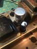
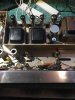
In the power supply, I used a CE / AES 40+20+20+20 @ 525V can that was short enough to fit. The 3 20uF sections are strung together to make the 60uF reservoir cap, and the remaining 40uF section takes the place of the 25uF section in the original (that supplies the 6AN8s). The original second can cap (a 30+30) was a smaller diameter, so a same-looking replacement was going to be tough. In the end, I got creative with a F&T 33uF+33uF @ 450V axial cap and a terminal strip. It obviously doesn't look original, but it doesn't look particularly bad, either, and you'll never see it anyway with the cover in place.

I've let the ceramic caps be for now, but I may tackle those at some point. I also have discrete components to make replacements for the PECs in the tone controls, but they seem to function perfectly well in their stock form, so that can be a project for another day.

Attached 8 ohm dummy loads and fired it up. Voltages on the power rail were reading somewhat high, despite the unit being plugged into my variac set to 117VAC. 385V at the 360V tap, for example. This is less than 10% over, so I'm not overly concerned at the moment... but eventually this thing is going to be connected sans variac to a freshly upgraded 120V mains supply, so this is something I'm going to want to revisit when I'm done with everything else. The PT has 2 6.3V windings, one for each channel, and I have noticed a discrepancy there -- one channel is getting 6.5V and the other is getting 6.1V. I'll have to dig a little deeper into that one.

I know some resistors have drifted out of spec (the 680K screen resistors on the 6AN8s, for example), and I plan to replace them. These are throwing some of the voltages at the tubes off, but not overly so. I suspect the out-of-spec resistors are skewing the current draw a bit, thus throwing off the power supply voltages.

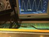
I set my function generator for 1KHz and hooked up the scope. I increased the input signal until I saw clipping visible at the output, and backed it off until the clip went away. Driving both channels, I measured 30Vpp, which is 10.6Vrms, which into an 8 ohm load is 14Wrms, which is what the AA-151 is rated for, so I'm pretty happy about that. My function generator is putting out 558mVpp to do that, which is in rounding error of 200mVrms, which also matches the original specs. Hey!

With the volume control turned all the way up, I am hearing some hum, which my scope tells me is 60Hz, and the typical tube hiss. So I guess I'm getting some heater supply noise from somewhere. It decreases with the volume control, which tells me it's coming from the 6EU7s. The original builder was a little sloppy with the filament supply twisting on those tubes, so that might be it if there are signal wires passing close by. The heater supply is floating on top of roughly 45V. It's the original circuit configuration -- a 150K - 33K voltage divider off the "205V source" tap of the power rail, which would be 37V if the voltages were spot-on... but as I noted above, they're not. Anyway, the hum is audible on even the Aux and Tuner inputs (I haven't tested the phono stage, which I know can be troublesome in this amp), so I have some work to do there. I've heard that doing a DC supply for the 6EU7s is a common modification on this model, but I feel like I should have a silent non-phono stage even without that.

This amp does have multiple AF amp stages, so even a little bit of noise at the very beginning is going to get magnified in a way that wouldn't be present with just a single AF amp stage before the output. The input is a little funky in that there is a voltage divider on the Aux and Tuner inputs good for -23.7dB, followed by a 27dB gain stage (the second half of the 6EU7), making for an effective gain of only like 1.5. I guess what they were trying to do there is to bring down the other input signals to the same level as the post-EQ mag phono signal, to simplify the signal path through the pre-amp. Personally, I would have been fine sacrificing a little input sensitivity to avoid putting the signal through an extra stage, but perhaps this was just easier with consideration for the capabilities of the other components that matched the AA-151 (like the tuner). My preference would be to remove the attenuator network and bypass the 6EU7 completely for Tuner / Aux, and just go right to the volume control and then the 6AU6 that drives the tone controls. I need to study the connections to the input selector switch a bit more to see if this can be done.

Volume pot was a little scratchy, so hosed it down with Deoxit, worked it around several times, and let it dry overnight. That fixed it right up. The tone pots were quiet, and the tone controls behave exactly as I expected. It's currently hooked up in the garage to my Sansui SP-1700s, and I've spent a few hours listening to a variety of music on it over the last few days, and despite the hum / hiss that's audible when the volume control is turned all the way up, it sounds very good at all of the listening levels I've tried. So, even with some out-of-spec parts, it's in fairly good shape. :thumbsup:
 

Attachments

  • IMG_3208.jpg
    IMG_3208.jpg
    82.2 KB · Views: 343
  • IMG_3210.jpg
    IMG_3210.jpg
    54 KB · Views: 330
  • IMG_3220.jpg
    IMG_3220.jpg
    143.5 KB · Views: 349
  • IMG_3228.jpg
    IMG_3228.jpg
    61.3 KB · Views: 332
  • IMG_3225.jpg
    IMG_3225.jpg
    82.7 KB · Views: 317
Register to hide this ad
Great job! All very consistent with things I've found and done with these units as well. One of the best things you can do is add an additional (even a resistive) filter network (say 50 - 100 ohms along with an extra filter cap) BEFORE the output tube B+ point. It will help to really tame the 120 Hz power supply noise -- particularly so during the initial warmup when the output tubes don't immediately (or largely) cancel each other out in the common mode connection of the OPT. Check the heater lead dress around the earlier stages to help address the 60 Hz hum.

Good luck with it!

Dave
 
Great job! All very consistent with things I've found and done with these units as well. One of the best things you can do is add an additional (even a resistive) filter network (say 50 - 100 ohms along with an extra filter cap) BEFORE the output tube B+ point. It will help to really tame the 120 Hz power supply noise -- particularly so during the initial warmup when the output tubes don't immediately (or largely) cancel each other out in the common mode connection of the OPT. Check the heater lead dress around the earlier stages to help address the 60 Hz hum.

Good luck with it!

Dave

Yes, I have noticed that as the output tubes warm up I get some 120Hz hum that almost immediately dies down to barely-perceptible. I assumed it was the lack of even current draw from the output tubes as they were coming online. I read your thread about the Heathkit AA-30 and how it's power supply was poorly configured in this regard as well. I may well decide the modify the power supply as you suggest.

As far as the line-level inputs go, I spent some time fiddling with those last night. As a backgrounder for those not familiar with the pre-amp section of the AA-151, each channel is configured like this:

Source -> [processing unit] -> input selector -> 2nd half 6EU7 -> volume control -> 6AU6 -> tone controls -> [AF amp / PI / output]

The "processing unit" for the Mag Phono stage is the 1st half of the 6EU7 + RIAA EQ. For the Aux, Tuner, and Xtal Phono, "processing unit" is a voltage divider acting as an attenuator, with a small cap bypassing the first leg of the divider, presumably to eliminate high frequency roll-off.

My theory was that since the effective gain of the first pre-amp section for the Aux and Tuner inputs up to the volume control is just 1.5 or so, there’s very little to be lost (except a considerable amount of hiss and hum) in bypassing the first pre-amp section (the 2nd half of the 6EU7) completely, i.e. sending the inputs of Aux and Tuner (and potentially Xtal Phono, because who has one of these anymore anyway) straight to the volume control and into the 6AU6.

To test the theory, I pulled the 6EU7s and then ran alligator wires from the Aux input jacks to the high sides of the volume pot, bypassing the attenuator network that's connected to those jacks. I fired up the amp and waited for it to warm up. As expected, the hum and hiss that was present with the volume at max was gone. So I backed off the volume control and started my music source, and it sounded perfectly fine. I didn’t check the input sensitivity, but on paper it goes from 200mVrms to 300mVrms. I can totally live with this.

So, this modification turns out to be fairly simple, from a mechanical perspective, if you ignore the Mag Phono input:
  1. Remove the first leg of the input attenuator from the input jack and replace with a short jumper wire (because the shielded cables are attached to terminal strips). For the Aux and Tuner inputs, this is a 470K resistor that is bypassed by a 33pF N750 ceramic cap. The the Xtal Phono input, this is a 2.2M resistor bypassed by a 10pF NP0 cap.
  2. Remove the second leg of the input attenuator from the rear of the input selector switch. Aux / Tuner, a 33K resistor. Xtal Phono, a 220K resistor. All that’s needed is to snip these resistors off.
  3. Disconnect the existing wires from the high sides of the volume pot.
  4. Disconnect the .1uF caps from the input selector switch, and connect that switch terminal to the corresponding volume pot high terminal (for right or left).
At this point, you have 3 line-level inputs with an input sensivity of 300mVrms. The 6EU7s are now unused and can be removed from their sockets (assuming this doesn’t increase the filament voltages too much).

It’s worth noting that the caps disconnected in step 4 connect the output of the input selector to the grid of the 2nd 6EU7 stage, which is seemingly redundant when you look at the schematic. Maybe attempting to soften noise from the switch?

Anyway, if you wanted to still have the Mag Phono input, you would have to disconnect the output of the first half of the 6EU7 from the input selector and connect it to the free lead of the .1uF cap you removed from the input selector previously. The wires that you previously disconnected from the high-side of the pot should then be connected to the Mag Phono terminals on the input selector. This is, of course, ignoring any modification that you might want to make to the Mag Phono stage — mine is crazy noisy, yikes. A complete re-do of this part of the pre-amp is probably warranted.

Anyway, I think I’m going to make this change to my unit. Keeping it “original” would be nice, but having a better sounding unit would be nicer, and as I mentioned before, I don’t need the Mag Phono stage for my intended use of this amp.
 
So, this modification turns out to be fairly simple, from a mechanical perspective, if you ignore the Mag Phono input:
  1. Remove the first leg of the input attenuator from the input jack and replace with a short jumper wire (because the shielded cables are attached to terminal strips). For the Aux and Tuner inputs, this is a 470K resistor that is bypassed by a 33pF N750 ceramic cap. The the Xtal Phono input, this is a 2.2M resistor bypassed by a 10pF NP0 cap.
  2. Remove the second leg of the input attenuator from the rear of the input selector switch. Aux / Tuner, a 33K resistor. Xtal Phono, a 220K resistor. All that’s needed is to snip these resistors off.
  3. Disconnect the existing wires from the high sides of the volume pot.
  4. Disconnect the .1uF caps from the input selector switch, and connect that switch terminal to the corresponding volume pot high terminal (for right or left).

Oops, it's not quite this simple. The rear section of the input selector grounds de-selected inputs, so some resistance at the switch is required for inputs that aren't selected. I think what I would probably want to do is to ground the switch though a 470K resistor rather than a wire, and then also add a 470K resistor across the low side of the pot and the high side of the pot. When selected, the 1M volume pot would be in parallel with the resistor across it, and when de-selected, the return resistance for the input would be 470K as it was in the original Aux / Tuner circuit.
 
On my AA-151, I bypassed the input attenuater and 6EU7 for the high level inputs and I also bypassed the tone controls. The result is audibly significant and very worthwhile. Highly recommended.

Frontwide.JPG RearviewAA-151.JPG
 
Last edited:
On my AA-151, I bypassed the input attenuater and 6EU7 for the high level inputs and I also bypassed the tone controls. The result is audibly significant and very worthwhile. Highly recommended.

Are you using the Mag Phono section at all? I'd be interested in more information about how you have it wired up, exactly. By "bypassing the tone controls", do you mean that you're skipping the 6AU6 stage altogether and sending the signal from the volume pot directly to the 6AN8 pentode section?
 
Upon further inspection, the Mag Phono stage in the AA-151 looks to essentially be the classic RCA circuit with only a few very minor tweaks (and the intervening input selector).
 
Are you using the Mag Phono section at all? I'd be interested in more information about how you have it wired up, exactly.
Yes, I am using the Mag Phono. I did the modification in 1988, some 28 years ago. My memory is a little fuzzy. I do remember that I used the 6AU6 tube socket location to install a cathode follower after the two stage phono amplifier. The 6EU7 was changed to a 12AX7 because I had a lot of 12AX7 and only a few 6EU7. I used a loop feedback, for the equalization components, similar to that used in the Audio Research SP-6.

By "bypassing the tone controls", do you mean that you're skipping the 6AU6 stage altogether and sending the signal from the volume pot directly to the 6AN8 pentode section?
Yes, that is exactly what I did. So, a high level signal fed into a high level input goes to the selector switch, then directly to a volume control (100kΩ), then directly to the gride of the 6AN8A. This is a lot cleaner than the original circuit. It sounds a lot better too.

Sorry, I do not have any inside photos.
 
Last edited:
Ok, I'm thinking through the pre-amp changes a bit more. I got to thinking -- with my current scheme of a 470K return resistor between the input selector switch and ground, that doesn't really provide any isolation between the inputs the way the stock configuration does (470K between the jack and the selector, with a direct shunt to ground at the selector).

So, looking for guidance, I decided to peek at a few other examples... I took a look at the Dynaco PAS-3X schematic, and the input selectors there don't appear to bother with any return resistance at all, instead simply shunting the de-selected signals directly to ground. At the very least, that seems a little anti-social from the perspective of whatever is driving those de-selected inputs. The Eico HF-81 seems to do the same thing. Furthermore, these well-known examples, in the de-selected case, don't seem to provide any isolation between inputs whatsoever (in the sense that they're all shunted directly to ground, so realistically, no foreign signal is ever going to make it back to one of the other inputs).

Am I over-thinking this? Seems like this is going to very heavily load up any de-selected input sources that happen to be connected and powered on.

I don't imagine this will be much of an actual problem with my intended usage of the unit (only rarely will anything be connected to something other than Aux), but I'd prefer to do this thing at least approximately right without it being a one-off hack job :)
 
Well, I finally wrapped up this project before heading to Yosemite for a week. I'm really happy with how it turned out. I left the tone controls in the circuit and am using the original PECs for now, because they seem to be performing perfectly fine. It sounds quite nice and will be just perfect in the master bedroom with the Klipsch RB-61 II bookshelf speakers I have.

Here is a description of what was done. All component names reference the Sam's Photofact schematic (Folder 8 Set 583).

Replacing the coupling capacitors and any out-of-spec resistors is implied.

Power supply changes
The first filter capacitor can was replaced with:
This is a 40uF+20uF+20uF+20uF @ 525V multi-section can cap. The 3 20uF sections are tied together in parallel for a total of 60uF and replace C1A. The 40uF section replaces C1B.

The second filter capacitor can was replaced with:
This is a 33uF+33uF @ 450V multi-section axial cap. These are replacements for C2A and C2B. The capacitor was mounted to a terminal strip which is secured to one of the mounting holes for the original can. The cap protrudes though the chassis in the space the original can occupied. The negative lead for the cap is connected to a wire that runs back down though the hole to the underside of the chassis and connects to the terminal strip. See photos in post #1 of the thread.

Per @dcgillespie's suggestion, the wire connecting C1A and the output transformers was replaced with a 47 ohm 5W resistor and a 100uF 450V cap. This completely eliminated the small amount of hum that was audible at startup. I ended up having to locate the extra cap far away (over by the output stage's cathode bypass cap) due to space constraints.

Due to one of the convenience outlets on my unit being faulty, I removed it from the circuit. There is now only one un-switched convenience outlet.

The mains cord was replaced with a 3-wire grounded variety. The safety ground is connected to the C1 ground tab, which is very solidly secured to the chassis. C37 was removed.


Pre-amp changes
In order to greatly reduce / eliminate the noise and hum from the high-level inputs (Aux, Tuner, Xtal Phono), the pre-amp section has been modified to bypass the 2nd 6EU7 pre-amp stage. This results in the input sensitivity changing from 200mVrms to 300mVrms.

Background: the high-level inputs are fed through a -23.7dB attenuating voltage divider to bring them down to the same level as the Mag Phono input post-EQ. Then all signals are fed through the 2nd 6EU7 pre-amp stage which has a gain of 27dB. Thus the effective gain for the high-level stages (well, Aux and Tuner, anyway) is only 1.5. With such a low amount of gain, and with modern line-level sources easily capable of driving the amplifier to full power, it makes sense to bypass all of this nonsense completely. At the same time, since no one has crystal phonographs anymore, I converted that input into a 3rd line-level input. I have to admit that there was a certain elegance to Heathkit's original design, as it allows for some simplicity in the source switching.

I found that the Mag Phono section was quite noisy, and since my intended application for this unit doesn't require it, I decided to make my life a little easier and simply disconnect that section for now. If I ever decide to sell the unit, I'll overhaul the phono section and it's interaction with the input switching section.
  1. Remove the first leg of the attenuators from the input jacks R6+C8 (Aux left), R7+C7 (Tuner left), R8+C6 (Xtal left), R31+C23 (Aux right), R33+C22 (Tuner right), R35+C21 (Xtal right). Use short lengths of wire to connect the jacks to the corresponding terminal strip locations where the shielded cable is connected.
  2. Remove the second leg of the attenuators from the input selector switch, R57, R58, R59, R32, R34, R36. It's not clear from the schematic, but these resistors are connected to ground via the switch's ground connector (pins 10 and 4). Note that when a source is de-selected, it's position on the switch is shunted to ground through pin 10 or 4, and thus in the stock configuration, the first leg of the attenuator acts as the return resistor for de-selected inputs. Note that in the new configuration, there is no return resistance. De-selected inputs are shunted directly to ground. This appears to be similar to how stand-alone pre-amps such as the Dynaco PAS-3X and Eico HF-81 are configured.
  3. Remove the .1uF coupling caps between the outputs of the input selector switch and the 2nd half of the 6EU7, C12 and C27.
  4. Remove existing wires from the high sides of the volume pot, R1A and R1B.
  5. Connect the outputs of the input selector switch to the corresponding high side terminals of the volume pot.
  6. Remove the 6EU7s from their sockets and store for use another day, V1 and V6.
With these changes, there are now 3 stereo line-level inputs with an input sensitivity of 300mVrms. These inputs have an impedance of 1M ohms (via the volume pot) when selected, and are a direct-shunt-to-ground when de-selected. The Mag Phono input is not functional without additional modifications.

Output stage changes
The speaker phasing switch has been removed from the circuit. Speakers are now connected directly to the appropriate terminals for each channel.
 
Last edited:
Very nice and detailed work. Congrats.

And I am sure these little EL84 tubes produce a lot more power then they look, right ?
 
Very nice and detailed work. Congrats.

And I am sure these little EL84 tubes produce a lot more power then they look, right ?

Thanks :) And, yah, EL84s are great tubes. The world is truly a better place because of them :) And I'm using my favorite EL84 flavor in this unit (Sovtek EL84Ms).
 
I totally agree about the EL84/6BQ5s/7189s, etc. I'm always glad to return to them. My various little late 50s monoblocs using variations on the Mullard 5-10 theme absolutely sing with the right transformers.
 
Do you have any pics or what did you do with the tone control network ? Just started messing around with my aa 151 .Trying to get aplan going
 
Do you have any pics or what did you do with the tone control network ? Just started messing around with my aa 151 .Trying to get aplan going

I didn't do anything to the tone control network... that part of my AA-151 worked just fine and continues to do so.
 
I didn't do anything to the tone control network... that part of my AA-151 worked just fine and continues to do so.
The 151 is one of my favorite vintage amps. In my rebuild, i did away with the tone controls and the 6au6. I simply bypassed the lot . The sound was cleaner without that circuit. I did keep the phono stage. I also installed the Broskie "garter circuit" and that seemed to be a noticeable improvement as well.
Just started messing around with my aa 151 .Trying to get aplan going
There are lots of solder joints which can be bypassed by using the component leads directly going from part to part instead of to a solder lug instead. You can eliminate needless connections which keeps signal integrity. Just use teflon tubing on the component leads to prevent shorts. Look into the "garter circuit" implementation as it will not require any additional components from what is already in the amp, just the added resistors and caps. It seems to me that they made the layout with that circuit in mind.
 
Back
Top Bottom